64,909 views
 Juniper Firewall ScreenOS Basics (CJFV)
ScreenOS Concepts & Terminology
The following document is based on ScreenOS v5.4.0r7.0
– Interface = connection to a specific subnet. An interface is assigned an IP address only if firewall is operating in L3 mode. Default interface names can vary on different Netscreen devices.
– Zone : logical grouping of subnets and interfaces. All devices within a zone share the same security requirements
– Firewall functionality is based upon policies. Policy specifies which traffic is to be permitted to pass through the firewall. Policies are implemented on a per zone basis : leaving one zone and entering another zone
– Virtual Router = logical routing construct. Each VR has its own routing table and routing logic. Routing part of kernel/firewall engine.
– Forwarding table : used to determine outbound interface for a particular packet
– Virtual System : logical division of the device into multiple administrative areas
– Firewalls track traffic based on flows and sessions (= 2-way flows)
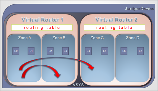
A Netscreen OS based device consists of
– One or more Virtual Systems (VSYS)
– Each VSYS contains one or more Virtual Routers (VR)
– Each VR contains
* One routing table
* One or more zones
Each zone contains
– One or more interfaces
– Optional policies within a zone (intrazone)
* Policies between zones within the same VR
– A VSYS can have policies between zones in different VR’s
A policy can only be applied to traffic between two different zones
Exception : if you enable "Block Intra-subnet traffic" on a specific interface, you can create policies within a zone as well. This behaviour is disabled by default, and would require proper routing to be set up
Command Line conventions
When configuring the device from CLI, you must enter a ‘save’ command in order to write the changed configuration to disk. When using the GUI, settings are saved automatically when you click "Apply" or "OK"
Most configurations can be defined using ‘set’ and ‘unset’. You can see configuration parameters using ‘get’
A ? (question mark) will show (context sensitive) help
You can use tab completion and abbreviated commands
If you want to see the current configuration, use ‘get conf’
If you want to see the current system information, use ‘get system’
You can filter the output of a command by using | incl ‘searchpattern’
You can use up&down arrows to browse through already used commands.
Managing the device config, backup and firmware updates
You can reset to factory-default settings using
unset all
Erase all system config, are you sure y/[n] y
reset
Configuration modified, save? [y]/n  n
System reset, are you sure y/[n]  y
In reset ...
The first command ‘unset all’ will reset the saved config, not the running config.
After entering the reset command, you must answer ‘n’ to the question to save the modified config, otherwise you would be saving the running config again to the saved config.
Note : root password and certificates are not reset by the ‘unset all’ command
Backup the configuration to a tftp server :
save config from flash to tftp 192.168.0.102 <filename>
Note : the Juniper firewall does not provide for a scheduled task/crontab engine. This means that you cannot schedule a backup and store the backup file on a tftp server. However, you can do it the other way around (connect from a server and download the file from the filesystem)
1. Create a read only administrator account on the firewall
set admin user "ReadOnlyAdminBackup" password "TheReadOnlyPassword" privilege read-only

save
2. Download pscp from http://www.chiark.greenend.org.uk/~sgtatham/putty/download.html
Note : some scp clients try to use sftp first, but this is not supported by screenos. Make sure, if you decide to use another scp client than pscp.exe, to verify that the client supports setting a parameter that forces the use of scp.
3. Enable scp on the firewall :
set scp enable

save
3. Place the pscp.exe on a server that is allowed to access the firewall over ssh/scp
4. Create a batch file on the server that looks like this :
pscp -scp -l ReadOnlyAdminBackup -pw "TheReadOnlyPassword"

    192.168.0.1:ns_sys_config d:\backups\ssg550_backup.cfg
5. Create a folder on the server called d:\backups
6. Use the scheduled tasks on the server to schedule this script. The first time, run the command yourself. pscp will prompt you to accept a host key, so you’ll need to run this command manually at least once.
The filesystem on a SSG device looks like this :
firewall1-> get file
    flash:/CONFIG.BIN                     112
    flash:/$NSBOOT$.BIN               9554671
    flash:/golerd.rec                       0
    flash:/certfile.cfg                  8425
    flash:/envar.rec                       45
    flash:/license.key                    361
    flash:/expire.rec                      23
    flash:/ns_sys_config                19615
    flash:/dnstb.rec                       41
    flash:/usrterms.txt                   515
    flash:/prngseed.bin                    32
    flash:/attacks.sig                 201470
Restore the configuration from a tftp server :
save config from tftp 192.168.0.102 <filename> to flash
save config from tftp 192.168.0.102 <filename> merge
‘to flash’ = config will be active at next boot
‘merge’ = config will be merged and activated right away – use with caution !
NEVER perform an update/config restore using the GUI – always use the CLI !
Backup the Operating System :
save software from flash to tftp 192.168.0.102 <filename>
Upgrade the Operating System :
save software from tftp 192.168.0.102 <filename> to flash
Always read the release notes – sometimes, a new bootloader is required. Reboot the device after performing the software upgrade. Make sure the upgrade process is not interrupted or you might cause irrepairable damage to the system.
Get OS version :
get sys | incl Software
Software Version: 5.4.0r7.0, Type: Firewall+VPN
Reboot device :
reset
Recovery of the device :
– Restore firmware at boot time. If you have a corrupted flash image, but the bootloader still works, you can interrupt the boot process ("Hit any key to run loader" -> Press any key during the first couple of seconds of the boot process), and upload a new software version from a tftp server. You will need to set a local (self) IP address and the IP address of the tftp server – which needs to be on the same subnet – during the restore wizard. You will be prompted to save the file to flash, and whether you want to run the downloaded image.
– Reset to factory defaults and restore config to flash
– System (asset) recovery :
* Login using serial number as username & password
* Use pinhole on some devices :
– Press until flashing light changes to orange
– Release and count 3 seconds, then press again until flashing red
– All leds will flash, device will reboot
If you want to use the last procedure, this functionality has to be enabled on the device :
set admin device-reset
set admin hw-reset
The asset recovery procedure will allow you to overcome the problem of a lost password, however this procedure is quite destructive. It will remove all settings (including root password and certificates) from the device, so you’ll need to reconfigure the device, or restore a recent backup file. You can see when an asset recovery has been performed on the device by looking at the control serial number in the output of a ‘get sys’
get sys
Product Name: SSG-550
Serial Number: 999999999999 , Control Number: 00000000
Hardware Version: 0000(0)-(00), FPGA checksum: 00000000, VLAN1 IP (0.0.0.0)
Software Version: 5.4.0r7.0, Type: Firewall+VPN
Feature: AV-K
Every time an asset recovery is performed, the Control Number is increased by one.
Zones & Interface configuration
On a SSG-550, these are the default zones :
firewall1-> get zone
----------------------------------------------------------------------
  ID Name               Type    Attr    VR          Default-IF   VSYS
   0 Null               Null    Shared untrust-vr   hidden       Root
   1 Untrust            Sec(L3) Shared trust-vr     null         Root
   2 Trust              Sec(L3)        trust-vr     null         Root
   3 DMZ                Sec(L3)        trust-vr     null         Root
   4 Self               Func           trust-vr     self         Root
   5 MGT                Func           trust-vr     null         Root
   6 HA                 Func           trust-vr     null         Root
  10 Global             Sec(L3)        trust-vr     null         Root
  11 V1-Untrust         Sec(L2) Shared trust-vr     v1-untrust   Root
  12 V1-Trust           Sec(L2) Shared trust-vr     v1-trust     Root
  13 V1-DMZ             Sec(L2) Shared trust-vr     v1-dmz       Root
  14 VLAN               Func    Shared trust-vr     vlan1        Root
  15 V1-Null            Sec(L2)        trust-vr     l2v          Root
  16 Untrust-Tun        Tun            trust-vr     hidden.1     Root
You can create your own zones and assign them to a VR. Every Virtual Router has its own routing table. In standard configurations, you’ll have multiple zones, but only one Virtual Router (trust-vr). If you are using dynamic routing protocols and you want to separate routing tables, you may need multiple Virtual Routers.
After creating a custom interface, you’ll have to assign the interface to a zone. Then you can assign an IP address to an interface. You can only assign an IP address after an interface has been assigned to a zone.
Don’t use 255.255.255.255 as a subnetmask for the IP address of an interface. Use the networks’s subnetmask, so the firewall can determine the "local subnet"
Initial device configuration
Connect, change passwords, create admin accounts
– Connect to the console using serial connection (9600bps, 8 bit, no parity, 1 stop bit, no flow control)
– Default username & password : netscreen / netscreen
(Change the password right away. Pay attention : you cannot recover the netscreen password easily, so don’t forget this password !).
set admin password "ThisIsANewButBadPassword"
save
Optionally, you can change the default administrator account. In this example, I’m changing the username to "administrator"
set admin name netscreen "administrator"
save
Create administrator account and assign rights (read-only or read-write)
set admin user "username" password "password" privilege all
set admin user "readonlyuser" password "readonlypassword" privilege read-only
save
By default, the internal database is used for admin authentication, but you can use an external resource (Radius, ldap, …) for admin authentication as well.
Set minimum password length to 8 and number of admin attempts to 2
set admin password restrict length 8
set admin access attempts 2
save
If you want to restrict "root" login to console only, use
set admin root access console
save
You can get all users and all ssh users, using the following commands :
get admin user
get admin ssh all
Set hostname
set hostname "firewall1"
save
Set zones & interfaces
By default, the device has 3 zones : Trust, Untrust and DMZ. The interface in Trust mode is set to nat mode by defualt, all other interfaces are in route mode. By default, the device allows outbound access ‘From Trust to Untrust) and blocks incoming access (default policy : deny)
I recommend not to use any of these 3 zones, but to create your own zones, and assign your interfaces to your custom zones. I also do not recommend using interfaces in nat mode, but use route mode instead.
Create 2 zones : One zone for Internet, one zone for your LAN, and assign the zones to a VR :
set zone "Internet"
set zone "Internet" vrouter trust-vr

set zone "Lan"
set zone "Lan" vrouter trust-vr

save
Assign interface ethernet0/1 to Internet, and interface ethernet0/2 to Lan.
set interface ethernet0/1 zone "Internet"
set interface ethernet0/2 zone "Lan"
save
See zone configuration :
firewall1-> get zone
Total 16 zones created in vsys Root - 10 are policy configurable.
Total policy configurable zones for Root is 10.
------------------------------------------------------------------------
  ID Name               Type    Attr    VR          Default-IF   VSYS
   0 Null               Null    Shared untrust-vr   hidden       Root
   1 Untrust            Sec(L3) Shared trust-vr     null         Root
   2 Trust              Sec(L3)        trust-vr     null         Root
   3 DMZ                Sec(L3)        trust-vr     null         Root
   4 Self               Func           trust-vr     self         Root
   5 MGT                Func           trust-vr     null         Root
   6 HA                 Func           trust-vr     null         Root
  10 Global             Sec(L3)        trust-vr     null         Root
  11 V1-Untrust         Sec(L2) Shared trust-vr     v1-untrust   Root
  12 V1-Trust           Sec(L2) Shared trust-vr     v1-trust     Root
  13 V1-DMZ             Sec(L2) Shared trust-vr     v1-dmz       Root
  14 VLAN               Func    Shared trust-vr     vlan1        Root
  15 V1-Null            Sec(L2)        trust-vr     l2v          Root
  16 Untrust-Tun        Tun            trust-vr     hidden.1     Root
 100 Lan                Sec(L3)        trust-vr     ethernet0/2  Root
 101 Internet           Sec(L3)        trust-vr     ethernet0/1  Root
The zone name has to be unique across all VR’s
Assign Lan interface a private static IP address, assign Interface a static IP address or DHCP IP address :
set interface ethernet0/2 ip 192.168.0.1/24

set interface ethernet0/1 ip 1.1.1.1/29
set interface ethernet0/1 dhcp client enable
save
Tip : if you need to define multiple interfaces in the same IP subnet, you’ll have to enable this first in the vrouter
set vrouter trust-vr ignore-subnet-conflict
save
Note : Pay attention to the subnetmask when configuring a firewall interface. Don’t use /32 or the firewall won’t work.
Set both interfaces in route mode
set interface ethernet0/1 route
set interface ethernet0/2 route
save
set interface ethernet0/2 phy ?
auto                 auto negotiation
full                 force full duplex
half                 force half duplex
holddown             holddown time
link-down            bring down link

set interface ethernet0/2 phy full ?
1000mb               1000Mbps
100mb                100Mbps
10mb                 10Mbps
Activate license, configure routing and anti-spoofing
set route 0.0.0.0/0 gateway 1.1.1.2
set dns host dns1 2.2.2.2 src-interface ethernet0/1
save
firewall1-> exec license-key update
License key was retrieved successfully.
License keys have been updated.
You must reset the device for the new setting to take effect.
firewall1-> save
firewall1-> reset
After rebooting, you can verify that the key was installed correctly using
firewall1-> get license-key
di_db_key           : JDkdLZidzoad9ZçjdklDIODiodaodiaOODIDZAdkdlazdD93+D
                      DKJ393jdLDKlcdkdLKZCnCZALDIdzidldjidLDZEIDJIZIODOD
                      DZKJLDLLIEDiODIJDELlkkLD/
                      bdazjlDIZDlldiIED0O93jdKLDZJIDO3DOJEIOLDJKLLDKDKDK
                      DKDJKLDlID9D9DKldjdklDJIDIDOZDNSQCCBZJK2E238ldklde
                      DZKALldiç3IK3LLjdkl30DJKLDL3ZJJKLL/
                      DKJLKddlzlzjkLDIZIlazkalJDII3CBNQDMJKDLKMkdlekldek
                      DZKLjdlkJD/DJKLDL3LJDKL3IOMOMKDLK==
expire date: 2009/01/1
Model:              Advanced
Sessions:           128064 sessions
Capacity:           unlimited number of users
NSRP:               ActiveActive
VPN tunnels:        1000 tunnels
Vsys:               None
Vrouters:           8 virtual routers
Zones:              512 zones
VLANs:              150 vlans
Drp:                Enable
Deep Inspection:    Enable
Deep Inspection Database Expire Date: 2012/01/01
(don’t bother – I have used a random string as db_key in my example…)
set route 192.168.1.0/24 gateway 192.168.0.10 permanent
save
set vrouter YourOwn-vr route 192.168.0.0/24 interface ethernet0/3 gateway 10.1.1.1

save
get route
You will see an entry for the IP address of every ethernet interface, with type "H". This is not a real route and will not be used during route evaluation. When debugging, these host entries will be referred to as "SELF"
Equal cost multipath routing is allowed
ScreenOS supports source-based and destination-based routing, and supports RIP, OSPF and BGP
firewall-> get route ip 192.168.1.15

Dest for 192.168.1.15

--------------------------------------------------------------------------------

trust-vr : => 192.168.1.0/24 (id=16) via 192.168.0.10 (vr: trust-vr)

Interface ethernet0/2 , metric 1
firewall1-> unset route 4.4.4.0/24
total routes deleted = 1
L2 mode : based on address list entries
set zone "Internet" screen ip-spoofing

save
If you want to check for reverse-path routes to drop or allow traffic, use this command :
set zone "Internet" screen ip-spoofing drop-no-rpf-route

save
Restrict management to/from certain IP addresses and on certain management services
Management services :
– Telnet, SSH, HTTP(s), snmp, ping, ident
– Can be enabled/disabled per interface and optioanlly set to a virtual IP address on the interface (manage ip)
– Traffic for these management services can be allowed from certain IP addresses only (manager-ip)
– Always disable ident, unless you have problems with AS400 RPC connections
First, disable management services on all interfaces :
unset interface ethernet0/1 manage
unset interface ethernet0/2 manage
unset interface ethernet0/1 ip manageable
unset interface ethernet0/2 ip manageable
save
Create a virtual IP address on the Lan interface (192.168.0.2) to allow local administrators to connect :
set interface ethernet0/2 manage-ip 192.168.0.2set interface ethernet0/2 ip manageablesave
You can see the virtual IP address that is used to host the management services using this command :
get int ethernet0/2 | incl manage
manage ip 192.168.0.2, mac 0010.dbe2.c300
Enable management services on Lan interface :
set admin http redirect
set interface ethernet0/2 manage ssh
set interface ethernet0/2 manage ssl
set ssl encrypt 3des sha-1
set interface ethernet0/2 manage web
save
If you want to disable one of the management services (e.g. disable ping to the Lan interface), use
unset interface ethernet0/2 manage ping

save
If you want to allow management on all services, use this command :
set interface ethernet0/2 manage
Only allow traffic from management station 192.168.0.5 Note : configure this via the console cable, as you may cut off your own connection if you don’t specify your own IP address first.
set admin manager-ip 192.168.0.5 255.255.255.255
save
You can see the IP addresses that are allowed to access the management services using the following commands :
get sys | incl "Mng Host"

Mng Host IP: 192.168.0.5/255.255.255.255

  get admin manager-ip

Mng Host IP: 192.168.0.5/255.255.255.255
You can define up to 6 IP addresses as manager-ip
Set console timeout. Default = 10 minutes, recommended : 5 minutes :
set console timeout 5
save
Tip : you can get the open/listening ports on the device using the “get socket” command.
Set up NTP, DNS, SNMP and Syslog
NTP :
set ntp server 192.168.0.3
set ntp server src-interface ethernet0/2
set ntp timezone 1
set clock timezone 1
set clock ntp
save
get clock

exec ntp update
The last command will force a manual ntp update
DNS :
set dns host dns1 192.168.0.4 src-interface ethernet0/2
set domain mydomain.com
set dns host schedule 04:00 interval 4
save
The dns host schedule interval defines the cache refresh time for DNS hostnames that are defined in the address list.
If you already had a DNS entry because of the license key installation, you can remove that entry using an unset command :
unset dns host dns1
SNMP :
set snmp community "MyROCommunity" Read-Only Trap-on traffic version v1
set snmp host "MyROCommunity" 192.168.0.100 255.255.255.255 src-interface ethernet0/2 trap v1
set snmp port listen 161
set snmp port trap 162
save
Syslog :
set syslog config "192.168.0.101"
set syslog config "192.168.0.101" facilities local0 local1
set syslog src-interface ethernet0/2
set syslog enable
save
Address Lists and Policies
Default policy is defined in "Global" Zone (default deny). By default, deny will be applied, but you won’t see this when querying the device. It is recommended to set the global policy to any any deny, that way you can see the global policies if you want to
firewall1-> get policy all | incl Global
No global policy!Default deny.
firewall1-> set policy global any any deny
firewall1-> save
set address "Lan" "Proxyserver1" 192.168.0.200 255.255.255.255 "Proxy Server 1"
set address "Lan" "LanNetwork1" 192.168.0.0 255.255.255.0 "Local Network 1"
set address "Lan" "LanNetwork2" 192.168.1.0 255.255.255.0 "Local Network 2"

save
You can create an address multiple times, and in multiple zones at the same time. Suppose you have a remote host that can be reached via 2 different routes over 2 different interfaces, that are in different zones, then you’ll need to define the same host twice.
You can group addresses using the GUI or CLI :
set group address "Lan" "LocalNetworks" add "LanNetwork1"
set group address "Lan" "LocalNetworks" add "LanNetwork2"
Next, you can create custom services. The device is already pre-loaded with some services, so verify that the service does not exist yet.
set service "MyCustomService" protocol tcp src-port 0-65535 dst-port 1234-1234
save
set policy from "Lan" to "Internet" "ProxyServer1" ANY "MyCustomService" nat src permit

save
get policy from "Lan" to "Internet"
Debugging & Troubleshooting Policies
get dbuf info set dbuf sizesave
firewall1-> clear dbuf
firewall1-> unset ffilter
filter 0 removed
firewall1-> unset ffilter
invalid id
debug flow basic
get dbuf stream
Optionally, you can send the entire buffer to a text file on a tftp server using
get dbuf str > tftp 192.168.0.102 debug.log
firewall1-> set ffilter ?
<return>
dst-ip               flow filter dst ip
dst-port             flow filter dst port
ip-proto             flow filter ip proto
src-ip               flow filter src ip
src-port             flow filter src port
Logical AND :
– enter options on the same line
– all conditions must be present
set ffilter src-uip 1.1.1.1 dst-ip 2.2.2.2 ip-prot 6
– enter options on separate lines
– any condition can be present
set ffilter src-ip 1.1.1.1 dst-ip 2.2.2.2 ip-prot 6
set ffilter src-ip 2.2.2.3
set ffilter dst-port 80
get ffilter
firewall1-> get console
Console timeout: 10(minute), Page size: 22/22, debug: buffer
privilege 250, config has not been changed!, default save prompt on exit/reset: yes
ID State  Duration Task Type   Host
 0 Login       439 21309696 SSH    192.168.137.120:62596
 1 Logout        0 21314736 Local
 2 Logout        0 21303816 Local
 3 Logout        0 21284496 Local
firewall1-> unset console dbuf
firewall1-> get console
Console timeout: 10(minute), Page size: 22/22, debug: console
privilege 250, config was changed and not saved!, default save prompt on exit/reset: yes
ID State  Duration Task Type   Host
 0 Login       454 21309696 SSH    192.168.137.120:62596
 1 Logout        0 21314736 Local
 2 Logout        0 21303816 Local
 3 Logout        0 21284496 Local
firewall1-> set console dbuf
firewall1-> get console
Console timeout: 10(minute), Page size: 22/22, debug: buffer
privilege 250, config was changed and not saved!, default save prompt on exit/reset: yes
ID State  Duration Task Type   Host
 0 Login       464 21309696 SSH    192.168.137.120:62596
 1 Logout        0 21314736 Local
 2 Logout        0 21303816 Local
 3 Logout        0 21284496 Local
set policy id 1
set log
exit
save
clear alarm traffic
clear alarm event
clear led alarm
set policy id 1
set count
exit
save
get counter policy 1 <time>
get tech support > tftp 192.168.0.102 get_tech_support.txt
Address Translation Basics
ScreenOS supports 2 types of Address Translation : Interface based or policy based. As stated earlier, I do not recommend using interface based address translation. Interface based address translation
– puts ingress interface in NAT mode
– source IP address is translated to IP address of egress interface
– is easy but allows no flexibility whatsoever
– unidirectional only
– default setup : from Trust to Untrust and from DMZ to Untrust
You can turn off interface based address translation by putting all interfaces in route mode.
When using policy based nat, you’ll have to apply NAT to every rule. This may require some discipline and concentration, but it also allow maximum flexibility and has more features than "nat for dummies" interface based nat.
Policy based nat can be used from any zone to any zone, based on a policy. It allows for unidirectional NAT (nat-src, nat-dst, VIP) and bidirectional NAT (MIP). There are several options available for when and how you want to perform NAT :
– application based
– number of routable addresses
– number of internal devices and servers
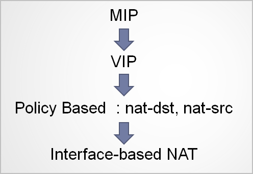
There are 4 main types of policy based nat :
nat-src : translate source address to another source address. Typically used to allow hosts within private network to access internet
nat-dst : translate destination address. Typically used to translate public IP to a private IP (when a private server needs to be accessible from the internet)
VIP (Virtual IP) : One to Many mapping that statically associates public address with many internal addresses, based upon ports/applications
MIP (Mapped IP) : One to One mapping : static association of a public IP with a private IP
nat-src
Unidirectional, has 2 modes : egress interface IP or DIP
Best known for allowing private IP addresses to access the internet via public IP address of firewall.
When using the egress interface mode, it essentially performs the same way as interface based nat.
nat-src can use DIP as well :
– defined on egress interface (can be tunnel interface as well !)
– custom specified IP, a range of IP’s (round robin), or a IP-Shift range (careful for overflow ! Shift : same amount of IP’s on both sides of the connection)
– IP (or range) must be in same subnet as
* Primary IP or egress interface
* Secondary IP of egress interface
* Extended IP on egress interface (which can be in different subnet as primary or secondary IP !)
– Can be used on multiple policies
– Max 252 DIP address sets across all interfaces, and 254 addresses per DIP set
– Cannot contain the primary IP itself or another address (MIP, VIP)
– Port translation : always enable if you want to avoid conflicts, leave disabled if there is a specific reason (e.g. Sometimes IPSec requires source and destination ports to be set to 500 at all times. Result : only 1 concurrent connection to same destination IP is possible)
– First create DIP on interface, then use in (each) policy
nat-dst
One-to-one mapping
Many-to-one mapping
Many-to-many mapping
Port translation (fixed port, set by admin)
One-to-one, unidirectional
Example :
– Source : remote public IP, destination : “public” IP on your firewall
– After translation : Source : unchanged, destination : internal IP, on all ports
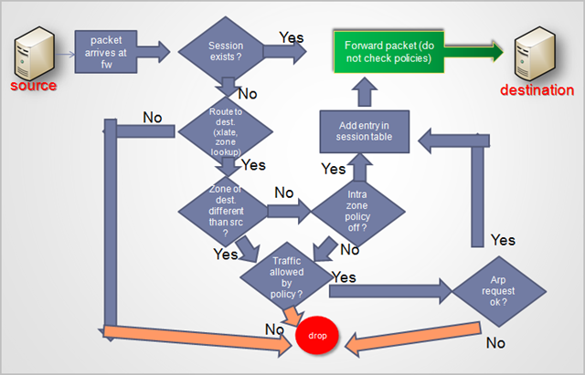
Watch out : policy (with nat-dst rule) only becomes effective when traffic flows between zones, However, public IP is in “Untrust” zone (Furthermore, it is a host entry, and host entry routes are not used in the "5 tuple" process – see packet handling diagram earlier in this post)
Solution :
– Create address list (host) entry for public IP/32 in your Lan zone ! (or use a secondary IP and create address list entry to secondary IP)
– Add static route to the public IP/32 and point route to interface (not gateway) in your “Lan” zone
– Create policy from Internet to Lan, from ANY to Host Entry in Trusts zone (which points to public IP) and invoke nat-dst
One-to-many
Virtual IP (VIP)
Only works when the interface is in the Untrust zone. If you’re not using Untrust zone (as recommended by me :) ), then you can accomplish the same thing using nat-dst.
You cannot use the real Public IP. The VIP IP must be in the same subnet as the public IP though.
Create set of Public IP / Private IP+Port combinations within a VIP
Used to allow on or more multiple services to be reachable from other zone, using a single IP
Example :
—Real Public IP : 1.1.1.1, VIP : 1.1.1.2, internal network = 192.168.0.0/24
—Port 21 on 1.1.1.2 must be mapped to 192.168.0.1 on port 21
—Port 80 on 1.1.1.2 must be mapped to 192.168.0.2 on port 8080
—Port 515 on 1.1.1.2 must be mapped to 192.168.0.3 on port 515
—Remote client only uses 1.1.1.2 as destination address (which is the VIP)
Configuration : create a VIP on the public interface
No routing or host entry required. Only use a policy and use the VIP address in the destination field.
Which ports need to be allowed in the policy ? Port 21, 80 and 515 ? Or port 21, 8080 and 515 ?
Answer : 21, 80, 515. The firewall will handle the port translation itself.
One-to-one, bidirectional
MIP
– No port translation
– Defined on outward facing interface
– (Target/Host)Address can be defined in any subnet, it does not need to be associated with any of the interfaces. As long as the firewall and upstream routers can route to that IP, it will work
– Config :
Create MIP (public IP + IP of host to route traffic to. Host IP : set subnetmask to /32 (If you use something else, you’ll do IP shifting)
Create policy and invoke MIP
Note on NAT : Using NAT may become quite complex. I could write an entire blog post on NAT alone, so if you have specific questions, don’t hesitate to contact me directly.
NAT application precedence
Authentication
ScreenOS supports two types of authentication :
– Firewall authentication (this requires that traffic matches a policy to trigger the login dialog). This policy must permit at least one of the following protocols : HTTP, Telnet, FTP. The firewall will basically perform a "mitm" to present you with an authentication login page.
– WebAuth : requires the user to browse to a designated webpage first and logon before a policy is applied.
You can find more information on how to set up WebAuth in conjunction with Windows IAS Radius on the following blog post on this website : Using Active Directory and IAS based Radius for Netscreen WebAuth authentication
The alarm led
If you notice that the alarm led on your device turns red, then it may be caused because screening is enabled, and one of the following events occurred :
Emergency:
Syn Attack
Tear Drop Attack
Ping of Death
Alert:
Winnuke Attack
IP Spoof Attack
IP Source Route Attack
Land Attack
ICMP Flood
UDP Flood
Port Scan Attack
Address Sweep
Policy Deny Alarms
The led will turn red if one of these attacks was detected. You can clear the red led using ‘clear led alarm’
© 2008 – 2021, Peter Van Eeckhoutte (corelanc0d3r). All rights reserved.
Similar/Related posts:
 Building IPSec VPN with Juniper Netscreen ScreenOS (CJFV)
Using 2 internet links with Juniper screenos Firewalls to separate traffic (pbr) and apply traffic shaping
Windows XP L2TP over IPSec dialup client VPN to a Juniper ScreenOS firewall, using Certificates
Juniper ScreenOS BGP Basics : a simple iBGP test case
Juniper : Setting up an IPSec VPN tunnel between a Juniper Netscreen firewall/vpn device and a Cisco VPN device
Building IPSec VPN with Juniper Netscreen ScreenOS (CJFV)
Using 2 internet links with Juniper screenos Firewalls to separate traffic (pbr) and apply traffic shaping
Windows XP L2TP over IPSec dialup client VPN to a Juniper ScreenOS firewall, using Certificates
Juniper ScreenOS BGP Basics : a simple iBGP test case
Juniper : Setting up an IPSec VPN tunnel between a Juniper Netscreen firewall/vpn device and a Cisco VPN device
2 Responses to Juniper Firewall ScreenOS Basics (CJFV)
Donate

Your donation will help funding server hosting.