70,208 views
 Building IPSec VPN with Juniper Netscreen ScreenOS (CJFV)
A few days ago, I have posted some ScreenOS basics on this blog. Today, it is time to take it one step further and to look at setting up and especially troubleshooting IPSec VPN’s with Juniper Netscreen devices.
The need for VPN
A VPN can be defined as the simulation of a private connection by tunneling traffic between 2 private locations. The mail tunneling protocols are L2TP, GRE and IPSec.
If we want to tunnel traffic over a public network, we are faced with some issues. We want to keep the date secure & hidden (confidentiality), we need to ensure that data has not been changed (integrity) and we’d like to make sure that the data really comes from the advertised source (authentication).
What are the available solutions for these 3 challenges ?
Confidentiality : Encryption
Data is encrypted/decrypted using keys :
– Symmetric (secret) key. Same key is used for encryption and decryption
* 40bits to 1024bit keys (fast, widely used for bulk data encryption)
* DES, 3DES, AES
* Juniper has ASIC that provides DES & 3DES. AES does not require ASIC because it is a faster protocol
* Because both sides use the same key, key management becomes a huge issue.
Symmetric keys are most commonly used in IPSec VPNs because of its good performance.
– Asymmectric (public & private) key : private key is used for encryption, mathematically related public key is used for decryption.
* Public key encryption : 512bits to 2048 bits (the larger, the more secure, but the slower as well.)
* RSA, DH (Diffie Hellman)
* Slow
* Mostly used only to transmit session keys
– Reversible
Integrity : Hashing
This is a one-way algorithm. You cannot determine the orginal data from the hash value. This hash value (result of of the hashing operation) is fixed-length (depends on the algorithm) :
* MD5 : 128bit length
* SHA : 160bit length
MD5 is less secure than SHA (collision attack. In theory, SHA is vulnerable to this too, but because of the length it would take longer to find a colliding couple)
As a result : If you want to use MD5 for hashing, you would need a PreSharedKey of 35 characters or more to make it a little bit more secure. Therefore I do not recommend using MD5 unless you really really have to.
The PreSharedKey that is used during IPSec authentication is hashed.
Source Authentication : HMAC
"Hashed Method Authentication Code"
This is the only place in the communication where a PSK is used
Sender adds hashed Pre Shared Key to data
Receiver appends same hashed key to data before sending back
Hashes are compared
Key is never transmitted along with the data, however I would still strongly advise to use a very very long PSK. And as stated before, Use SHA-1 or better as hashing algorithm (because MD5 is less secure).
I have briefly discussed the 3 solutions for setting up a safe VPN. I have introduced ‘keys’ as part of encryption and hashing processes. The use of keys introduces yet another challenge : we need to find a save way to exchange the keys that will be used during the VPN session. Earlier in this document, I have explained why symmetric keys are used often for IPSec VPN, but since the keys must be same at both sides of the tunnel, we need to determine/exchange these keys in a safe way.
Key Exchange
There are 2 main solutions for key exchange : manual or automatic
Manual key exchange is not only subject to possible configuration errors (if you have to type over a 1024bit key, it’s likely that you’ll make some mistakes. Furthermore, because of this issue, in reality, these keys won’t be changed often…)
Automatic exchange is what we are looking for. But how can we safely exchange the keys over a public connection ? If anyone would be able to see the key, that person would be able to decrypt the data as well.
The solution for this is Diffie-Hellman. It solves the distribution problem using public/private key pairs. Only the public keys are sent across the network.
How does it work ?
DH uses 5 sets of very large prime numbers (and a generator). These sets are called "Group1", "Group2", "Group3", "Group4" and "Group5".
A Juniper device supports Group1 (768bit prime), Group2 (1024bit prime) and Group5 (1536bit prime). Note : Because of performance issues, it is not recommended to use Group5 on software clients. It should, however, work fine for VPN tunnels between appliances. In reality, Group2 is most commonly used.
Both sides of the tunnel (peers) must be configured to use the same DH Group, otherwise, the key generation process will fail.
These are the main steps that happen during the DH Key Exchange :
1. Each device generates a public/private key pair. These 2 keys are mathematically related.
2. The public keys are exchanged
3. On both sides, the local private and remote public key are used in a mathematical process to form a common session key. Since the public & private key pairs are mathematically related, the result of this computation is an identical key at both sides. This key can now be used as session key. It is known at both sides of the tunnel, but it was never exchanged. Perfect, we have solved the Key Exchange issue.
We know understand the basics of keys and key exchange, so we are ready to take this one step further.
IPSec basics
Before we start looking at configuring IPSec VPNs, we need to understand IPSec, which will make it easier to implement and troubleshoot IPSec based VPNs.
ESP and AH
IPSec works at the IP layer and basically uses 2 protocols : ESP and AH
ESP (Encapsulating Security Protocol) = IP Protocol 50 (RFC 2406)
– Provides for Confidentiality, Integrity and Authentication.
– uses DES, 3DES, AES, etc for encryption, and MD5/SHA to provide hashing security services.
– Header can be modified, because all payload is encapsulated (important for NAT)
AH (Authentication Header) = IP Protocol 51 (RFC 2402)
– Only provides for integrity and authentication, but no encryption
– It cannot pass through NAT in transport mode, because the original header would be modified.
– Is faster than ESP, but not as secure (no encryption, remember !)
There are 2 IPSec modes : Tunnel mode and Transport mode. I’m not going to discuss the diferences here. We’ll mostly work with Tunnel mode IPSec in this document, which allows you to tunnel traffic between networks (whereas transport mode tunnels traffic between hosts)
IPComp
This is the third element from the IPSec suite. This is used to compress data inside the VPN tunnel. I will not discuss this feature in this document.
IKE – Security Associations
An IPSec tunnel is established using IKE (Internet Key Exchange), over UDP 500
This process establishes Security Associations (SA) :
– Negotiates "proposals" containing encryption and authentication algorithms. (Example: remember : before the two sides of the tunnel can create/exchange a common session key, they need to agree on which DH Group they will be using, and which Encryption and Hashing algorithm will be used. These settings are referred to as the "proposals")
– Creates encryption and authentication keys automatically, which provides for rekeying. ?
– Provides gateway identity
Note : Encryption and Authentication algorithm negotiation happens both in Phase 1 and 2 of the setup of a IPSec tunnel. I’ll explain these 2 phases later on.
In short, a Security Association (SA) is a set of policies and keys that are used to protect the information between the two peers. Since a device can have multiple IPSec tunnels, a SA needs to be uniquely identified. Otherwise, the device would not know which key needs to be used to decrypt traffic. This is achieved through the use of a SPI (internal index number), the destination IP address and the security protocol (ESP / AH)
During Phase1, the SA process is bidirectional. This SA is called the ISAKMP SA.
During Phase2, it is unidirectional. This SA is called the IPSec SA. This means that you can restrict the Phase2 connection (ESP) to one direction or both directions.
In short : A full blown IPSec connection consists of 3 SA’s : 1 x Phase 1, 2 x Phase 2 (one for inbound, one for outbound connections)
SA’s are stored in the SA database. Each entry has the name of the VPN, the remote gateway IP, SPIs for each direction, security protocol that is agreed upon, the encryption and authentication algorithms and the keys.
More info can be found at IPsec- IKE, Internet Key Exchange
Proxy ID’s
In Phase 2 of the IPSec tunnel setup, IKE ID’s are generated locally. These are the Proxy ID’s. This identifies which SA is used for the VPN, and is used to link multiple subnets to the same VPN. There are always 2 proxy ID’s : a local proxy ID and a remote proxy ID. These proxy ID’s actually refer to the local and remote IP address/network and subnetmask that will travel across the tunnel. Each local proxy ID must match the remote proxy ID from the other peer, and each remote proxy ID must match the local proxy ID of the other peer. These matches must be perfect and exact. ?
Examples :
"1.1.1.0/255.255.255.0" does not equal "1.1.1.0/24". ?
"1.1.1.1" does not equal "1.1.1.1/32"
If the proxy ID’s don’t match, Phase 2 of the IPSec connection won’t work.
These proxy ID’s may sound like a limitation, but fortunately it’s not always mandatory to hardcode/specify them by hand. You can set up VPN connections between Juniper devices without specifying proxy ID’s. The proxy ID’s will then be generated using the source and target firewall policy objects at both ends of the tunnel. VPN connections with non-Juniper devices such as Nortel VPN and Cisco do require hardcoded proxy ID’s. Since you can only specify one local and one remote proxy ID per connection, it may become a bit cumbersome to set up many to many network connections over a single VPN tunnel. But it works.
Keep in mind : there must be an exact match. Proxy ID mismatches is the most common cause of VPN establishment failures.
Finally – What are IKE Phase 1 and Phase 2 all about ?
In Phase 1, the peers establish a secure authenticated channel :
– DH is used to generate a symmetric key that is common to those 2 peers
– Phase 1 has 2 modes : main (when both sides have a static IP) and aggressive (when one side does not have a static IP, or when one of the devices sits behind an outbound NAT device (so the IP address of the device is not the IP address used to connect to the remote host). These could be remote end users, or even VPN appliances). When we discussed the contents of the SA, we noticed that the IP addresses were part of the SA. If one of the sides does not have a static IP, it cannot be included in the SA. Therefore, Aggressive mode is not as secure as main mode, but it is faster (only 3 packets, whereas Main mode = 6 packets)
A single Phase1 can be used to establish multiple Phase 2 connections. After all, Phase 1 only contains general information, and nothing about the source IP addresses, target IP addresses etc that need to travel through the VPN tunnel. This information is stored in Phase 2
As a sidenote : By default, Phase 1 is the only place where keys are exchange. But if you continue to use the same keys, it becomes less secure. You can use Perfect Forward Secrecy (PFS), which will use DH in Phase 2 as well, for rekeying.
Phase 1, IPSec tunnel establishment, in main mode :
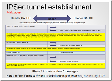 ?
?
(click on the image for larger view)
In Phase 1, aggressive mode, IP addresses are not validated (so basically anyone with a VPN client, knowing the PSK, would be able to connect to the VPN). In this scenario, the connection must be initiated by the host that does not have the static IP address. The first two packets negotiate the policy and exchange DH public values / nonces. This second packet (from the host with static IP going back to the host with non-static IP) also authenticates the responder (the ID hash will be compared with the locally configured peer ID). The Identification hash is sent in plain text.
The 3rd packet authenticates the initiator. Again, aggresssive mode is faster, but less secure. Try to avoid using aggressive mode if you can. And if you have to use it, use a very very strong PSK, and read this article : PSK Cracking using IKE Aggressive Mode 1. Basics-
Always verify the phase 1 modes on both ends of the device. Only the initiator needs to be in aggressive mode. Some Cisco devices use main mode by default but wil auto-fall back to Aggressive mode. It is advised to turn off this behaviour (and you should now why by now)
http://www.networkcomputing.com/922/922ws2side1.html
Phase 2, also called Quick mode, only has 3 packets.
During Phase 2, SAs are negotiated using the protected channel that was set up in Phase 1. The Proxy ID’s are used to identify which SA is referenced. If you’ve enabled PFS, then DH is used for rekeying. If you don’t want to use PFS, you need to set Juniper to Group0 for Phase 2.
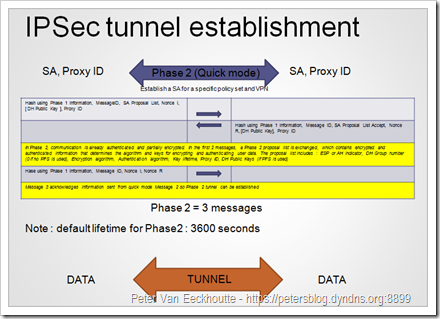
(click on the image for larger view)
After Phase 1 and Phase 2 are established, all traffic travels through the encrypted tunnel. From this point forward, a VPN is established and operational.
Both phases are also explained at http://www.ciscopress.com/articles/article.asp?p=25474&seqNum=7 and at http://www.ciscopress.com/articles/article.asp?p=24833&seqNum=6
Important
We have discussed the main components of an IPSec tunnel. We have talked about DH Groups, SA’s, Proxy ID’s, Encryption and Hashing protocols, lifetime settings etc. It is of the utmost importance to make sure all of these settings are configured exactly the same way at both sides of the tunnel. Don’t take for granted that settings such as lifetimes are the same by default – they may not be. Check and double check all settings if things don’t work as expected.
ScreenOS VPN IPSec implementation specifications
Juniper supports two types of VPN configurations, both based on the IPSec specifications as explained above : "Policy based VPN" and "Route based VPN". In essence, these 2 types use the same techniques under the hood, but the way the VPN is created/activated/triggered is different.
Policy based
Combine VPN tunnel with policy
Proxy ID based upon address book entries in policy. Port/Protocol from policy will be sent as well
Policy action is “tunnel”
Route based
Tunnel interface, routing is sent to tunnel interface
Proxy ID must be created per tunnel. Multiple sources, multiple targets = many tunnel definitions (Phase 2)
Policies separated from routing
Between Juniper devices, you can use any of these 2 modes. Between Juniper and other devices (Nortel, Cisco), you may need to use Policy based VPN’s or Route based VPN’s (sometimes one will work and the other won’t doesn’t, even with the same parameters…)
Tip : if you want to set up a VPN between a third party device, and you’re not sure what proposals they are using (DH Group, hashing, …), then all you need is the PSK from the other side. Put your Juniper device in "Accept all proposals" mode using ‘set ike accept-all-proposal’ , configure your end of the tunnel with the PSK ask the person at the other side to ping your network through their VPN device, and look in the log to see what the other side is sending as proposal. (don’t forget to turn ‘set ike accept-all-proposal’ off again after you have properly configured the proposals, using unset ike accept-all-proposal)
Policy based VPN setup components :
- Create Phase 1 (gateway) definition
- Create Phase 2, without proxy ID
- Define local and remote subnets in address book, put remote subnets in different zone
- Create policy from ‘local’ zone to ‘remote’ zone (from local subnets to remote subnets), action “tunnel”, choose VPN definition to be used. Since you need address list entries in order to create a policy, the objects needs to be in the same zone. So if the remote network is reachable via a VPN that uses the internet connection, it’s obvious that you create the remote network object in the Internet zone.
- No changes to routing table needed, just make sure routing to remote networks is ‘catched’ by the firewall, going to the zone that is used as destination zone in the policy
- Don’t use “multiple” source / destination addresses, create individual policies !
- Proxy ID’s are created from address book entries in the policy, so make sure they match with the networks defined on the remote gateway. When creating the P2 (Autokey IKE) definition, you can keep the local and remote proxy ID empty.
If is my recommendation to try to avoid using policy based VPN’s, unless you have to (because you are setting up a tunnel with a Nortel/Cisco device for example)
Route based VPN setup components :
- Create tunnel interface for each remote/local proxy ID combination, bind tunnel to interface used to apply NAT. If you are setting up a tunnel over the internet, make sure tunnel interface is in “Public/Untrust” zone
- Create routes towards remote networks and bind to tunnel interface
- Create Phase 1
- Create Phase 2 definitions for each subnet combination (Proxy ID) (and bind to individual tunnel interface -> must match route !)
- Create policy to allow traffic (e.g. from Trust to Public)
- If no proxy ID’s are used at the other side, then you don’t need to create tunnel interface/Phase 2 for each subnet combination. If proxy ID’s are used, you’ll have to fill them out in the Phase 2 (Autokey IKE) definition page.
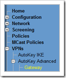
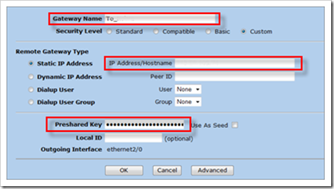
Set up Phase 1 : "Create Gateway"
Fill out the name of the Gateway, Fill out the IP address of the remote VPN gateway, and provide the Pre Shared Key
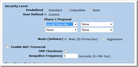
Set the security level to Custom and click "advanced"
Set the Phase 1 proposal (in my example, I’m using Group2, 3DES, SHA), Main Mode.
Save the setup
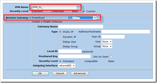
Now, create Phase 2 (Autokey IKE)
Fill out a name for the VPN, set the Remote Gateway to "Predefined" and select the Gateway that was created earlier
Click "advanced"
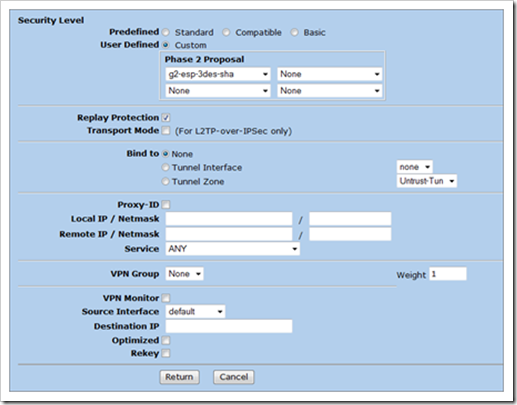
Select a Phase2 Proposal and select the DH group for PFS. If you don’t want to use PFS, set the Phase2 Proposal to nopfs-esp-3des-sha
Enable Replay Protection
Set the service to ANY
If you are creating a route based vpn, you’ll need to select your tunnel interface under "Bind To". In my example, I’m using policy based VPN, so I’ve selected "Bind to none"
(Note : If you are using route based VPN, you need to create your tunnel interface prior to creating the Phase 2 configuration.)
set interface tunnel.1 ip unnumbered interface ethernet0/2
save
For route based VPN : you need to create the route towards the remote network and send it to the tunnel interface
Trigger the VPN
Back to our policy based VPN example : In order to trigger the VPN, create objects (remotenetwork 192.168.133.0/24 and localserver 192.168.124.4), and create a rule From "Internet" to "LAN", source=remotenetwork, target=localserver, action = tunnel.)
In case of route based VPN : if you have created the tunnel interface in the right zone, created a router that points to the tunnel interface, and bound Phase2 to the tunnel interface, then the VPN will kick in when traffic is generated.
With route based VPN’s, the policy action to use is "permit" and not "tunnel" !
Troubleshooting IPSec VPN on Juniper
These are some commands that can be used to troubleshoot VPN’s :
IKE :
SA :
Phase1 and Phase2 process :
(works just like debug flow basic. You’ll need to start debugging, generate traffic, and stop debugging by pressing the ESC key. You can then see the contents of the debug buffer using ‘get dbuf str’
Troubleshooting Phase 1
Phase 2 cannot begin until Phase 1 is complete. If Phase 1 is complete, you’ll see a valid entry in the "ike cookie" list and you’ll see an active sa in the "get sa active" list.
Start with clearing the IKE cookie info :
Active: 1, Dead: 0, Total 3 102f/0003,
1.1.1.1:500->2.2.2.2:500, PRESHR/grp2/3DES/SHA, xchg(5) (To_RemoteOffice/grp-1/usr-1)
resent-tmr 16777218 lifetime 28800 lt-recv 28800 nxt_rekey 28786 cert-expire 0
initiator, err cnt 0, send dir 0, cond 0x0
nat-traversal map not available
ike heartbeat : disabled
ike heartbeat last rcv time: 0
ike heartbeat last snd time: 0
XAUTH status: 0
DPD seq local 0, peer 0
If all goes well, the "debug ike detail" output should indicate that Phase 1 has complete. If you did not enable debugging while the connection was initiated, you can get the status of Phase1 connections using ‘get ike cookies’
In my testlab, I have setup a VPN between 1.1.1.1 (remote Nortel Contivity gateway) and 2.2.2.2 (local Juniper gateway). The tunnel is used to encrypt traffic from 192.168.133.0/24 (remote network) to 192.168.124.4 (local server)
## 2007-11-27 21:53:41 : IKE<2.2.2.2> ****** Recv kernel msg IDX-52, TYPE-5 ******
## 2007-11-27 21:53:41 : IKE<2.2.2.2> ****** Recv kernel msg IDX-52, TYPE-5 ******
## 2007-11-27 21:53:41 : IKE<2.2.2.2> sa orig index<52>, peer_id<2>.
## 2007-11-27 21:53:41 : IKE<2.2.2.2> isadb get entry by peer/local ip and port
## 2007-11-27 21:53:41 : IKE<2.2.2.2> create sa: 1.1.1.1->2.2.2.2
## 2007-11-27 21:53:41 : getProfileFromP1Proposal->
## 2007-11-27 21:53:41 : find profile[0]=<00000005 00000002 00000001 00000002> for p1 proposal (id 5), xauth(0)
## 2007-11-27 21:53:41 : init p1sa, pidt = 0x0
## 2007-11-27 21:53:41 : change peer identity for p1 sa, pidt = 0x0
## 2007-11-27 21:53:41 : IKE<0.0.0.0 > create peer identity 087e9fd18
## 2007-11-27 21:53:41 : peer identity 7e9fd18 created.
## 2007-11-27 21:53:41 : IKE<0.0.0.0 > EDIPI disabled
## 2007-11-27 21:53:41 : IKE<2.2.2.2> Phase 1: Initiated negotiation in main mode. <1.1.1.1 => 2.2.2.2>
## 2007-11-27 21:53:41 : IKE<2.2.2.2> Construct ISAKMP header.
## 2007-11-27 21:53:41 : IKE<2.2.2.2> Msg header built (next payload #1)
## 2007-11-27 21:53:41 : IKE<2.2.2.2> Construct [SA] for ISAKMP
## 2007-11-27 21:53:41 : IKE<2.2.2.2> auth(1)
## 2007-11-27 21:53:41 : IKE<2.2.2.2> xauth attribute: disabled
## 2007-11-27 21:53:41 : IKE<2.2.2.2> lifetime/lifesize (28800/0)
## 2007-11-27 21:53:41 : IKE<2.2.2.2> Construct NetScreen [VID]
## 2007-11-27 21:53:41 : IKE<2.2.2.2> Construct custom [VID]
## 2007-11-27 21:53:41 : IKE<2.2.2.2> Construct custom [VID]
## 2007-11-27 21:53:41 : IKE<2.2.2.2 > Xmit : [SA] [VID] [VID] [VID]
## 2007-11-27 21:53:41 : IKE<2.2.2.2> Initiator sending IPv4 IP 2.2.2.2/port 500
## 2007-11-27 21:53:41 : IKE<2.2.2.2> Send Phase 1 packet (len=156)
## 2007-11-27 21:53:41 : IKE<2.2.2.2> Phase 2 task added
## 2007-11-27 21:53:41 : IKE<2.2.2.2> ike packet, len 140, action 0
## 2007-11-27 21:53:41 : IKE<2.2.2.2> Catcher: received 112 bytes from socket.
## 2007-11-27 21:53:41 : IKE<2.2.2.2> ****** Recv packet if
## 2007-11-27 21:53:41 : IKE<2.2.2.2> Catcher: get 112 bytes. src port 500
## 2007-11-27 21:53:41 : IKE<0.0.0.0 > ISAKMP msg: len 112, nxp 1[SA], exch 2[MM], flag 00
## 2007-11-27 21:53:41 : IKE<2.2.2.2 > Recv : [SA] [VID] [VID]
## 2007-11-27 21:53:41 : IKE<0.0.0.0 > extract payload (84):
## 2007-11-27 21:53:41 : IKE<2.2.2.2> MM in state OAK_MM_NO_STATE.
## 2007-11-27 21:53:41 : IKE<2.2.2.2> Process [VID]:
## 2007-11-27 21:53:41 : IKE<2.2.2.2 > Vendor ID:
## 2007-11-27 21:53:41 : 42 4e
## 2007-11-27 21:53:41 : IKE<2.2.2.2> receive unknown vendor ID payload
## 2007-11-27 21:53:41 : IKE<2.2.2.2> Process [VID]:
## 2007-11-27 21:53:41 : IKE<2.2.2.2 > Vendor ID:
## 2007-11-27 21:53:41 : af ca d7 13 68 a1 f1 c9 6b 86 96 fc 77 57 01 00
## 2007-11-27 21:53:41 : IKE<2.2.2.2> Process [SA]:
## 2007-11-27 21:53:41 : IKE<2.2.2.2> Proposal received: xauthflag b4
## 2007-11-27 21:53:41 : IKE<2.2.2.2> auth(1)
## 2007-11-27 21:53:41 : IKE<2.2.2.2> xauth attribute: disabled
## 2007-11-27 21:53:41 : IKE<2.2.2.2> Phase 1 proposal [0] selected.
## 2007-11-27 21:53:41 : IKE<2.2.2.2> SA Life Type = seconds
## 2007-11-27 21:53:41 : IKE<2.2.2.2> SA lifetime (TV) = 28800
## 2007-11-27 21:53:41 : IKE<0.0.0.0 > dh group 2
## 2007-11-27 21:53:41 : IKE<2.2.2.2> DH_BG_consume OK. p1 resp
## 2007-11-27 21:53:41 : IKE<2.2.2.2> Phase 1 MM Initiator constructing 3rd message.
## 2007-11-27 21:53:41 : IKE<2.2.2.2> Construct ISAKMP header.
## 2007-11-27 21:53:41 : IKE<2.2.2.2> Msg header built (next payload #4)
## 2007-11-27 21:53:41 : IKE<2.2.2.2> Construct [KE] for ISAKMP
## 2007-11-27 21:53:41 : IKE<2.2.2.2> Construct [NONCE]
## 2007-11-27 21:53:41 : IKE<2.2.2.2 > Xmit : [KE] [NONCE]
## 2007-11-27 21:53:41 : IKE<2.2.2.2> Initiator sending IPv4 IP 2.2.2.2/port 500
## 2007-11-27 21:53:41 : IKE<2.2.2.2> Send Phase 1 packet (len=184)
## 2007-11-27 21:53:41 : IKE<2.2.2.2> IKE msg done: PKI state<0> IKE state<1/0007>
## 2007-11-27 21:53:41 : IKE<2.2.2.2> ike packet, len 212, action 0
## 2007-11-27 21:53:41 : IKE<2.2.2.2> Catcher: received 184 bytes from socket.
## 2007-11-27 21:53:41 : IKE<2.2.2.2> ****** Recv packet if
## 2007-11-27 21:53:41 : IKE<2.2.2.2> Catcher: get 184 bytes. src port 500
## 2007-11-27 21:53:41 : IKE<0.0.0.0 > ISAKMP msg: len 184, nxp 4[KE], exch 2[MM], flag 00
## 2007-11-27 21:53:41 : IKE<2.2.2.2 > Recv : [KE] [NONCE]
## 2007-11-27 21:53:41 : IKE<0.0.0.0 > extract payload (156):
## 2007-11-27 21:53:41 : IKE<2.2.2.2> MM in state OAK_MM_SA_SETUP.
## 2007-11-27 21:53:41 : IKE<2.2.2.2> Process [KE]:
## 2007-11-27 21:53:41 : IKE<2.2.2.2> processing ISA_KE in phase 1.
## 2007-11-27 21:53:41 : IKE<2.2.2.2> Process [NONCE]:
## 2007-11-27 21:53:41 : IKE<2.2.2.2> processing NONCE in phase 1.
## 2007-11-27 21:53:41 : IKE<2.2.2.2> IKE msg done: PKI state<0> IKE state<1/a00000f>
## 2007-11-27 21:53:41 : IKE<0.0.0.0 > finished job pkaidx <0> dh_len<128> dmax<64>
## 2007-11-27 21:53:41 : IKE<0.0.0.0 > finished job d<5e8b4401><4b2f9969><90960ffd>
## 2007-11-27 21:53:41 : IKE<2.2.2.2> gen_skeyid()
## 2007-11-27 21:53:41 : IKE<2.2.2.2> MM
## 2007-11-27 21:53:41 : IKE<2.2.2.2> re-enter MM after offline DH done
## 2007-11-27 21:53:41 : IKE<2.2.2.2> Phase 1 MM Initiator constructing 5th message.
## 2007-11-27 21:53:41 : IKE<2.2.2.2> Construct ISAKMP header.
## 2007-11-27 21:53:41 : IKE<2.2.2.2> Msg header built (next payload #5)
## 2007-11-27 21:53:41 : IKE<2.2.2.2> Construct [ID] for ISAKMP
## 2007-11-27 21:53:41 : IKE<2.2.2.2> Use IPv4 address 1.1.1.1 as IKE p1 ID.
## 2007-11-27 21:53:41 : IKE<2.2.2.2> Construct [HASH]
## 2007-11-27 21:53:41 : IKE<2.2.2.2> Use IPv4 address 1.1.1.1 as IKE p1 ID.
## 2007-11-27 21:53:41 : IKE<2.2.2.2> ID, len=8, type=1, pro=17, port=500,
## 2007-11-27 21:53:41 : IKE<2.2.2.2> addr=1.1.1.1
## 2007-11-27 21:53:41 : IKE<2.2.2.2> throw packet to the peer, paket_len=64
## 2007-11-27 21:53:41 : IKE<2.2.2.2 > Xmit*: [ID] [HASH]
## 2007-11-27 21:53:41 : IKE<2.2.2.2> Encrypt P1 payload (len 64)
## 2007-11-27 21:53:41 : IKE<2.2.2.2> Initiator sending IPv4 IP 2.2.2.2/port 500
## 2007-11-27 21:53:41 : IKE<2.2.2.2> Send Phase 1 packet (len=68)
## 2007-11-27 21:53:42 : IKE<2.2.2.2> ike packet, len 120, action 0
## 2007-11-27 21:53:42 : IKE<2.2.2.2> Catcher: received 92 bytes from socket.
## 2007-11-27 21:53:42 : IKE<2.2.2.2> ****** Recv packet if
## 2007-11-27 21:53:42 : IKE<2.2.2.2> Catcher: get 92 bytes. src port 500
## 2007-11-27 21:53:42 : IKE<0.0.0.0 > ISAKMP msg: len 92, nxp 5[ID], exch 2[MM], flag 01 E
## 2007-11-27 21:53:42 : IKE<2.2.2.2> Decrypting payload (length 64)
## 2007-11-27 21:53:42 : IKE<2.2.2.2 > Recv*: [ID] [HASH] [NOTIF]
## 2007-11-27 21:53:42 : IKE<0.0.0.0 > extract payload (64):
## 2007-11-27 21:53:42 : IKE<2.2.2.2> MM in state OAK_MM_KEY_EXCH.
## 2007-11-27 21:53:42 : IKE<2.2.2.2> Process [ID]:
## 2007-11-27 21:53:42 : IKE<2.2.2.2> ID received: type=ID_IPV4_ADDR, ip = 2.2.2.2, port=0, protocol=0
## 2007-11-27 21:53:42 : IKE<2.2.2.2> ID processed. return 0. sa->p1_state = 2.
## 2007-11-27 21:53:42 : IKE<2.2.2.2> Process [HASH]:
## 2007-11-27 21:53:42 : IKE<2.2.2.2> ID, len=8, type=1, pro=0, port=0,
## 2007-11-27 21:53:42 : IKE<2.2.2.2> addr=2.2.2.2
## 2007-11-27 21:53:42 : IKE<2.2.2.2> Process [NOTIF]:
## 2007-11-27 21:53:42 : IKE<2.2.2.2> Received notify message for DOI <1> <24578>
## 2007-11-27 21:53:42 : IKE<2.2.2.2> Received initial contact notification and removed Phase 2 SAs.
## 2007-11-27 21:53:42 : clear phase 2 sa of peer To_RemoteOffice.
## 2007-11-27 21:53:42 : IKE<2.2.2.2> deactive p2 sa 48 send_delete 0
## 2007-11-27 21:53:42 : IKE<2.2.2.2> deactive p2 sa 47 send_delete 0
## 2007-11-27 21:53:42 : IKE<2.2.2.2> deactive p2 sa 49 send_delete 0
## 2007-11-27 21:53:42 : IKE<2.2.2.2> deactive p2 sa 50 send_delete 0
## 2007-11-27 21:53:42 : IKE<2.2.2.2> deactive p2 sa 51 send_delete 0
## 2007-11-27 21:53:42 : IKE<2.2.2.2> deactive p2 sa 52 send_delete 0
## 2007-11-27 21:53:42 : IKE<2.2.2.2> process notify exit with <0>.
## 2007-11-27 21:53:42 : IKE<2.2.2.2> completing Phase 1
## 2007-11-27 21:53:42 : IKE<2.2.2.2> sa_pidt = 7e9fd18
## 2007-11-27 21:53:42 : IKE<2.2.2.2> found existing peer identity 7e9fa6c
## 2007-11-27 21:53:42 : IKE<2.2.2.2> peer_identity_unregister_p1_sa.
## 2007-11-27 21:53:42 : IKE<0.0.0.0 > delete peer identity 0x7e9fd18
## 2007-11-27 21:53:42 : IKE<2.2.2.2> peer_idt.c peer_identity_unregister_p1_sa 509: pidt deleted.
## 2007-11-27 21:53:42 : IKE<2.2.2.2> Phase 1: Completed Main mode negotiation with a <28800>-second lifetime
The output above clearly shows 6 packets, so Phase is using main mode. Before setting up Phase 2, any ‘old’ Phase 2 SA’s are removed from the database, so a new Phase 2 SA can be created. Phase 1 ends with "Phase 1: Completed Main Mode negotiation with a <28800>-second lifetime" in my example.
If Phase 1 is not complete, check the following parameters on both peers :
– Gateway (peer) IP address (used as Phase 1 ID’s)
– Pre Shared Key
– lifetime (28800 seconds ?) If the default lifetime does not match the P1 definition at the other side, you can create your own P1 (and P2) proposal sets, and use those.
– DH Group (Group1 ? Group2 ? Group5 ?)
– DH Encryption Algorithm (DES ? 3DES ? AES ?)
– DH Hashing Algorithm (MD5 ? SHA ?)
You can get the Phase1 (gateways) using get ike gateway
Tip : if you want to bring down one tunnel, do a ‘get ike cookies’ to get the list of Phase 1, note the (remote) IP address of the tunnel you want to take down, and then run clear ike
If Phase 1 completes successfully, then the parameters listed above are set correctly. If the VPN still doesn’t work, then follow the next troubleshooting procedure :
Troubleshooting Phase 2
Again, ‘get ike detail’ is our friend here. This is an excerpt from the output, focussed on the Phase 2 communications :
## 2007-11-27 21:53:42 : IKE<1.1.1.1> Phase 2: Initiated Quick Mode negotiation.
## 2007-11-27 21:53:42 : IKE<1.1.1.1> Phase-2: start quick mode negotiation
## 2007-11-27 21:53:42 : IKE<1.1.1.1> Phase-2: no tunnel interface binding for Modecfg IPv4 address.
## 2007-11-27 21:53:42 : IKE<1.1.1.1> Create conn entry…
## 2007-11-27 21:53:42 : IKE<1.1.1.1> …done(new 5ac2cb73)
## 2007-11-27 21:53:42 : IKE<1.1.1.1> Initiator not set commit bit on 1st QM.
## 2007-11-27 21:53:42 : IKE<0.0.0.0 > dh group 2
## 2007-11-27 21:53:42 : IKE<1.1.1.1> DH_BG_consume OK. p2 init
## 2007-11-27 21:53:42 : IKE<0.0.0.0 > add sa list for msg id <5ac2cb73>
## 2007-11-27 21:53:42 : IKE<1.1.1.1> 0,0/0(0)/spi(51aba53a)/keylen(0)
## 2007-11-27 21:53:42 : IKE<1.1.1.1> Construct ISAKMP header.
## 2007-11-27 21:53:42 : IKE<1.1.1.1> Msg header built (next payload #8)
## 2007-11-27 21:53:42 : IKE<1.1.1.1> Construct [HASH]
## 2007-11-27 21:53:42 : IKE<1.1.1.1> Construct [SA] for IPSEC
## 2007-11-27 21:53:42 : IKE<1.1.1.1> Set IPSEC SA attrs: lifetime(3600/0)
## 2007-11-27 21:53:42 : IKE<1.1.1.1> atts<00000003 00000000 00000003 00000002 00000001 00000002>
## 2007-11-27 21:53:42 : IKE<1.1.1.1> proto(3)
## 2007-11-27 21:53:42 : IKE<1.1.1.1> Before NAT-T attr unmap: private tunnel = 1.
## 2007-11-27 21:53:42 : IKE<1.1.1.1> After NAT-T attr unmap: private tunnel = 1.
## 2007-11-27 21:53:42 : IKE<1.1.1.1> Policy have separate SA. Use P2 ID from policy sa (73).
## 2007-11-27 21:53:42 : IKE<192.168.124.4> IP<192.168.124.4> mask<255.255.255.255> prot<1> port<0>
## 2007-11-27 21:53:42 : IKE<1.1.1.1> Initiator P2 ID built:
## 2007-11-27 21:53:42 : IKE<192.168.133.0> IP<192.168.133.0> mask<255.255.255.0> prot<1> port<0>
## 2007-11-27 21:53:42 : IKE<1.1.1.1> Responder P2 ID built:
## 2007-11-27 21:53:42 : IKE<1.1.1.1> Construct [NONCE] for IPSec
## 2007-11-27 21:53:42 : IKE<1.1.1.1> Construct [KE] for PFS
## 2007-11-27 21:53:42 : IKE<1.1.1.1> Construct [ID] for Phase 2
## 2007-11-27 21:53:42 : id payload constructed. type(1),ip(047ca8c0),mask(ffffffff), prot(1), port(0)
## 2007-11-27 21:53:42 : IKE<1.1.1.1> Construct [ID] for Phase 2
## 2007-11-27 21:53:42 : id payload constructed. type(4),ip(0085a8c0),mask(00ffffff), prot(1), port(0)
## 2007-11-27 21:53:42 : IKE<1.1.1.1> construct QM HASH
## 2007-11-27 21:53:42 : IKE<1.1.1.1 > Xmit*: [HASH] [SA] [NONCE] [KE] [ID] [ID]
## 2007-11-27 21:53:42 : IKE<1.1.1.1> Encrypt P2 payload (len 292)
## 2007-11-27 21:53:42 : IKE<1.1.1.1> Initiator sending IPv4 IP 1.1.1.1/port 500
## 2007-11-27 21:53:42 : IKE<1.1.1.1> Send Phase 2 packet (len=300)
## 2007-11-27 21:53:42 : IKE<0.0.0.0 > proc_other_session_notify->
## 2007-11-27 21:53:42 : IKE<0.0.0.0 > process Notify Payload: doi(1), msg(24578), txt
## 2007-11-27 21:53:42 : IKE<1.1.1.1> Received initial contact notification and removed Phase 1 SAs.
## 2007-11-27 21:53:42 : IKE<1.1.1.1> IKE msg done: PKI state<0> IKE state<3/102f>
## 2007-11-27 21:53:42 : IKE<1.1.1.1> ike packet, len 96, action 0
## 2007-11-27 21:53:42 : IKE<1.1.1.1> Catcher: received 68 bytes from socket.
## 2007-11-27 21:53:42 : IKE<1.1.1.1> ****** Recv packet if
## 2007-11-27 21:53:42 : IKE<1.1.1.1> Catcher: get 68 bytes. src port 500
## 2007-11-27 21:53:42 : IKE<0.0.0.0 > ISAKMP msg: len 68, nxp 8[HASH], exch 5[INFO], flag 01 E
## 2007-11-27 21:53:42 : IKE<1.1.1.1> Create conn entry…
## 2007-11-27 21:53:42 : IKE<1.1.1.1> …done(new e2cbde43)
## 2007-11-27 21:53:42 : IKE<1.1.1.1> Decrypting payload (length 40)
## 2007-11-27 21:53:42 : IKE<1.1.1.1 > Recv*: [HASH] [NOTIF]
## 2007-11-27 21:53:42 : IKE<1.1.1.1> Process [NOTIF]:
## 2007-11-27 21:53:42 : IKE<1.1.1.1> Received notify message for DOI <1> <18>
## 2007-11-27 21:53:42 : IKE<1.1.1.1> ah-esp: notify has no matching QM record, mess_id in
## 2007-11-27 21:53:42 : IKE<1.1.1.1> WARN, Unknown Notify Message 18
## 2007-11-27 21:53:42 : IKE<1.1.1.1> process notify exit with <0>.
## 2007-11-27 21:53:42 : IKE<1.1.1.1> Delete conn entry…
## 2007-11-27 21:53:42 : IKE<1.1.1.1> …found conn entry(e2cbde43)
Some notes :
– Nortel expects service “ANY” when incoming VPN connection is setup, and then uses Statefull Inspection firewall to apply filtering once Phase1 and Phase2 are set up
– Juniper does send service as part of the Proxy ID exchange, so Nortel might complain about it
Solution : Set service to ANY for tunnel establishment, and use the firewall policy to filter traffic inside the tunnel; and verify that the proxy ID on both sides is set correctly.
General checklist for troubleshooting VPN between Juniper & Nortel :
* Subnets (local and remote) must be exact match at both ends of the tunnel, because they are used as proxy ID’s.
*Check lifetime for Phase 1 and Phase 2, must match on both gateways. (create custom P1/P2 proposals)
* Firewall policies must be exact match at both ends of the tunnel. Change Nortel firewall to permit the exact same services as what is defined on Juniper. (So if you allow ping on Juniper, the only allow ping on Nortel and vice versa)
* Enable “Nailed Up” on Nortel, this might help keeping the tunnel alive
* Turn off possible vendor specific options, such as compression etc
* Check routing on Juniper : routes must be set up using the exact ‘remote subnet’ definitions. If it still doesn’t work, then you will need to use route based VPN
## 2007-11-29 13:26:02 : IKE<1.1.1.1> IKE: Matching policy: gw ip <1.1.1.1> peer entry id<1>
## 2007-11-29 13:26:02 : IKE<0.0.0.0 > protocol matched expected<0>.
## 2007-11-29 13:26:02 : IKE<0.0.0.0 > port matched expect<0>.
## 2007-11-29 13:26:02 : ipvx = IPV4
## 2007-11-29 13:26:02 : rcv_local_addr = 192.168.124.4, rcv_local_mask = 255.255.255.255, p_rcv_local_real = 192.168.124.4
## 2007-11-29 13:26:02 : rcv_remote_addr = 192.168.133.0, rcv_remote_mask = 255.255.255.0, p_rcv_remote_real = 192.168.133.0
## 2007-11-29 13:26:02 : ike_p2_id->local_ip = 192.168.124.4, cfg_local_mask = 255.255.255.255, p_cfg_local_real = 192.168.124.4
## 2007-11-29 13:26:02 : ike_p2_id->remote_ip = 192.168.133.0, cfg_remote_mask = 255.255.255.0, p_cfg_remote_real = 192.168.133.0
## 2007-11-29 13:26:02 : IKE<1.1.1.1> Proxy ID match: Located matching Phase 2 SA <89>.
## 2007-11-29 13:26:02 : IKE<1.1.1.1> sa ID for phase 2 sa is <89>. IP version is 4.
## 2007-11-29 13:26:02 : IKE<0.0.0.0 > life (sec or kb): lcl 3600, peer 28800, set 3600.
## 2007-11-29 13:26:02 : IKE<0.0.0.0 > life (sec or kb): lcl 0, peer 0, set 0.
## 2007-11-29 13:26:02 : IKE<1.1.1.1> gen_qm_key()
## 2007-11-29 13:26:02 : IKE<1.1.1.1> load_sa_keys(): enter.
## 2007-11-29 13:26:02 : IKE<1.1.1.1> gen_qm_key()
## 2007-11-29 13:26:02 : IKE<1.1.1.1> load_sa_keys(): enter.
## 2007-11-29 13:26:02 : IKE<1.1.1.1> ikmpd.c 3668. sa ID for phase 2 sa is <89>. IP version is 4.
## 2007-11-29 13:26:02 : IKE<0.0.0.0 > spi hash node removed: type<2>,spi<51aba801>,ip<2.2.2.2>
## 2007-11-29 13:26:02 : IKE<0.0.0.0 > spi hash node removed: type<2>,spi
## 2007-11-29 13:26:02 : IKE<1.1.1.1> clean_all_sa_state_node_from_list->
## 2007-11-29 13:26:02 : IKE<1.1.1.1> no relocate earlier SA-state, not active.
## 2007-11-29 13:26:02 : IKE<1.1.1.1> key_modify: sa index <50> bk_idx <50>.
## 2007-11-29 13:26:02 : IKE<0.0.0.0 > insert_sa_state_to_spi_hash spi<04a8ab51>, sa_index<50>, Incoming
## 2007-11-29 13:26:02 : IKE<0.0.0.0 > insert_sa_state_to_spi_hash spi<0aca7ffb>, sa_index<50>, Outgoing
## 2007-11-29 13:26:02 : IKE<1.1.1.1> crypto_ctx 22, 8, 24, 8, 0, 0, 16, 0, 12, 48
## 2007-11-29 13:26:02 : IKE<1.1.1.1> modify esp tunnel: src (peer) ipv4 <1.1.1.1>
## 2007-11-29 13:26:02 : IKE<1.1.1.1> modifying esp tunnel: self
## 2007-11-29 13:26:02 : IKE<1.1.1.1> update auto NHTB status
## 2007-11-29 13:26:02 : IKE<1.1.1.1> after mod, out nsptunnel <05238b58>.
## 2007-11-29 13:26:02 : IKE<1.1.1.1> Phase 2 msg-id <59ca5ebc>: Completed Quick Mode negotiation with SPI <04a8ab51>, tunnel ID <89>, and lifetime <3600> seconds/<0> KB.
## 2007-11-29 13:26:02 : IKE<1.1.1.1> Application sa installed.
## 2007-11-29 13:26:02 : IKE<1.1.1.1> oakley_process_quick_mode():exit
## 2007-11-29 13:26:02 : IKE<1.1.1.1> IKE msg done: PKI state<0> IKE state<3/102f>
## 2007-11-29 13:26:03 : IKE<0.0.0.0 > dh group 2
## 2007-11-29 13:26:03 : IKE<1.1.1.1> nhtb_list_update_status: vpn VPN_To_RemoteOffice_Porto
## 2007-11-29 13:26:03 : IKE<1.1.1.1> ** link ready return 8
## 2007-11-29 13:26:03 : IKE<1.1.1.1> sa_link_status_for_tunl_ifp: saidx 50, preliminary status 8
## 2007-11-29 13:26:03 : IKE<1.1.1.1> nhtb_list_update_status: vpn VPN_To_RemoteOffice_Lisboa
## 2007-11-29 13:26:03 : IKE<1.1.1.1> ** link ready return 8
## 2007-11-29 13:26:03 : IKE<1.1.1.1> sa_link_status_for_tunl_ifp: saidx 49, preliminary status 8
## 2007-11-29 13:26:03 : IKE<1.1.1.1> nhtb_list_update_status: vpn VPN_To_RemoteOffice_Portimao
## 2007-11-29 13:26:03 : IKE<1.1.1.1> ** link ready return 8
## 2007-11-29 13:26:03 : IKE<1.1.1.1> sa_link_status_for_tunl_ifp: saidx 48, preliminary status 8
## 2007-11-29 13:26:03 : IKE<0.0.0.0 > finished job pkaidx <0> dh_len<128> dmax<64>
## 2007-11-29 13:26:03 : IKE<0.0.0.0 > finished job d
## 2007-11-29 13:26:03 : IKE<0.0.0.0 > BN, top32 dmax64 zero
## 2007-11-29 13:26:04 : IKE<0.0.0.0 > dh group 2
## 2007-11-29 13:26:04 : IKE<0.0.0.0 > finished job pkaidx <0> dh_len<128> dmax<64>
## 2007-11-29 13:26:04 : IKE<0.0.0.0 > finished job d<1b020ca5>
## 2007-11-29 13:26:04 : IKE<0.0.0.0 > BN, top32 dmax64 zero
## 2007-11-29 13:26:34 : IKE<1.1.1.1> Delete conn entry…
## 2007-11-29 13:26:34 : IKE<1.1.1.1> …found conn entry(bc5eca59)
Common Phase 1 and Phase 2 mistakes :
get event type 536
Proposal mismatch :
– "Phase 1 : retransmission limit has been reached" (this most likely indicates a proposal mismatch in Phase 1. Because Phase 1 has not been completed yet, no response is sent back to the originator, which eventually reports that the retransmission limit has been reached).
– "Phase 1 : Rejected proposals from peer. Negotiations failed"
– "Phase 2 : Received notify message fro DIO <1> <14>
– "Phase 1 : Rejected proposals from peer. Negotiations failed"
Solution : proposal list configured in phase 1 and/or phase 2 does not match on both gateways. Check PFS setting in Phase2 as well!
If you have troubles with the proposals, you can configure the Juniper to accept all proposals : set ike accept-all-proposals
Preshared Key mismatch : Correct the PSK and try again
No route information : both gateways needs to be able to contact each other, perhaps routing is not set up correctly.
Rejected initial Phase 1 packet from unrecognized peer gateway :
Possible Causes :
– Initiator uses dynamic IP, but tunnel is still in main mode.
– Peer gateway addresses don’t match
– Peer ID misconfigured (on gateway with dynamic IP, you need to set the local ID, on gateway with fixed IP, you need to set the peer ID. Both ID strings must match)
– Outgoing interface is incorrect
Phase 2: No policy exists for the proxy ID received: local ID <…..> remote ID <……>
Address book errors (proxy ID) : Address book entries do not match on both gateways (check subnetmasks as well !)
P2 Attributes not supported : This mostly happens between a Juniper and non-Juniper device (such as Nortel), and is caused because some vendor specific settings are enabled on the non-Juniper device (such as compression, vendor ID, etc)
Invalid cookie
## 2007-11-27 22:15:51 : IKE<75.137.56.20> Received notify message for DOI <1> <4>
This indicates that the gateway (peer) IP addresses do not match at both sides
Replay protection is not configured on both ends
Useful links on IPSec :
- http://www.unixwiz.net/techtips/iguide-ipsec.html
- http://technet2.microsoft.com/windowsserver/en/library/1e472f2f-14f2-47b0-8128-786f4f4c3a491033.mspx?mfr=true
- http://www.juniper.net/techpubs/software/erx/erx51x/swconfig-routing-vol1/html/ipsec-config5.html
- www.blackhat.com/presentations/bh-asia-01/rooster/rooster-ipsecindepth.ppt
- www.cs.fsu.edu/~breno/CIS-5357/fall2004/IPSEC.pdf
- http://www.sans.org/newsletters/cva/vol2_17.php
- http://www.boerderie.com/VPNdebugging.html
- http://kb.juniper.net/kb/documents/public/resolution_path/J_FW_VPN_Config_or_Trblsh.htm
© 2008 – 2021, Peter Van Eeckhoutte (corelanc0d3r). All rights reserved.
