26,959 views
 Juniper : Netscreen Remote Dial-UP VPN with AD Radius Authentication and route based VPN / tunnel interface
The following procedure explains how to set up a Juniper ScreenOS based firewall to accept Netscreen Remote Client VPN connections and authenticate users using Active Directory (Radius via Windows 2003 IAS or Windows 2008 NPS).
We’ll assume that all traffic to from the client to the 192.168.0.0/16 networks needs to pass via the client VPN tunnel. Clients will use dynamic IP addresses (either public or behind a nat router that is capable of handling IPSec passthrough)
The VPN connection must use the following encryption and hashing parameters and PSK :
- Phase 1 : aes-128, sha-1, DH Group2, PSK : This1sNot4GoodPSK3y
- Phase 2 : aes-128, sha-1, replay protection, PFS with DH Group2
Network layout :
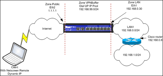
The Juniper firewall has 3 zones : Public (eth2, connected to the internet, static public IP), LAN (eth1, connected to the LAN) and a separate zone called VPNBuffer, not attached to any interface. This is just an empty zone, a placeholder, so we can create proper policies (instead of defining policies from Public to LAN, we will be able to use policies from VPNBuffer to LAN, thus separating the internet-to-lan traffic policies from the vpn-to-lan policies. It just looks better… )
All interfaces are in route mode.
In the LAN network, there is a Domain Controller at 192.168.0.6, which will be configured as IAS (Radius) server. (The IAS does not need to be a DC, just a domain member will do)
This is what needs to be done
- Juniper : Configure an auth server (Radius)
- Windows : Set up Radius
- IAS on Windows 2003 or
- NPS on Windows 2008
- Juniper : Define IP Pool / Subnet
- Juniper : Create tunnel interface
- Juniper : Set up routing
- Juniper : Define IKE user/group and External Group for XAuth (Radius)
- Juniper : Set XAuth defaults
- Juniper : Configure Phase 1
- Juniper : Configure Phase 2
- Juniper : Configure policies
- Client : Configure Netscreen Remote
- Client : Connect
Configure auth server
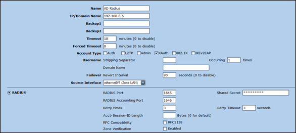
Configuration – Auth – Auth Servers – New
- Set a name for the Auth Server
- Set IP address of server that will be running IAS (Radius)
- Set account type to XAuth
- Set Source Interface to the LAN interface (eth1)
- Enable Radius and set Shared Secret
- Save new Auth Server
Windows 2003 : Set up IAS/Radius
As explained in one of my previous blog posts, IAS is a part of Windows Server. At this point, I will assume you have been able to install the IAS Component on your server, and that you have changed the authentication port to 1645, and the accounting port to 1646 (and that you have restarted the IAS service)
Under IAS, open “Radius Clients”, right-click and add a new Radius client. Enter the IP address of the LAN interface of the firewall (192.168.0.30 in our case. Note : if you have defined a manage-ip that is different than the interface IP, you will need to use this IP). Client-Vendor is Radius Standard. Enter the Shared Secret that was entered in the Juniper Auth Server definition. Press Finish to complete the creation of the client.
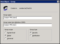
The final step is to create a policy where you will determine whether a given user should be granted access to VPN or not. You can use Windows AD Groups for this. First, in AD, create a group that will contain your VPN users.
Let’s say we’ll use a group called Juniper.VPN.Users, and added a couple of user accounts in there.
The idea is now to create an IAS policy that will allow members of this group to be granted access.
In IAS, open “Remote Access Policies” and remove any default policies that may be in there. (Just don’t delete the “Use Windows authentication for all users” under “Connection Request Policies” (which can be found under “Connection Request Processing”.
In the “Remote Access Policies” section, right-click and choose “New remote access policy”.
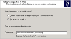
Click next at the welcome screen. Next, choose “Set up a custom policy” and provide a relevant name
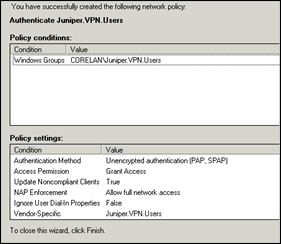
In the Policy Conditions Window, click “Add”. Select “Windows-Groups” and click “Add”. Click “Add” to add your newly created AD group. Click OK to save.
Click next. Select “grant remote access permission” and click next.
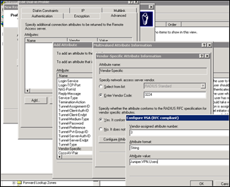
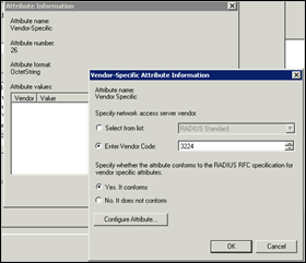
Click “Edit profile”. Go to the authentication tab. Make sure only PAP/SPAP is selected. In the Advanced Tab, remove the default attributes (Service-Type and Framed Protocol"). Click “Add” to add a new attribute. Select “Vendor-specific” and click Add to add a new attribute. Click Add to add a new value. Set Vendor Code to 3224, select “Yes, it conforms” and Click “Configure Attribute”
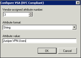
In the Configure VSA (RFC Compliant) screen, set Vendor-assigned attribute number to 3, set Attribute format to “string” and enter a string that will be sent to the Juniper firewall upon succesfull authentication. This string needs to match with the name of an external group that will be created on the Juniper. You are free to pick whatever string you like, but I usually use the name of the AD group (so I know that this group matches with an AD group). So we’ll set the string to “Juniper.VPN.Users”
Click OK to save, Click OK, click Close, click OK. Accept the warning. Click next and click Finish.
At this point, the Windows environment is ready to authenticate VPN users. If you want to set up Radius on a Windows 2008 server instead of 2003, read the next chapter (otherwise, you can skip the next chapter and jump right back to the Juniper configuration)
Windows 2008 : Set up NPS/Radius
Of course, if you are running Windows 2008, you can also use NPS (which replaces IAS) to achieve the same goal. This is how it works :
First, add the required roles on the server that will acts as Radius server. This does not need to be a DC. If the server is part of the domain, it will work just fine
Open Server Manager and add a role
Select Network Policy and Access Services and click next
Click next again
Select Network Policy Server (NPS) and click next
Click Install. Click ‘close’ when the installation has completed.
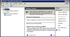
Open a MMC and add the NPS snap-in (Local Computer)
First, change the Radius port to 1645. Right-click on NPS (Local) and choose properties
Go to the ports tabsheet and set Authentication to port 1645 only, and accounting to port 1646 only. Click OK to save. use the Action pane on the right to stop and start the NPS service (or use “Services” to restart the NPS service)
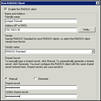
Open Radius Clients under NPS (Local) – RADIUS Clients and Servers, right-click and choose ‘New Radius Client’
Fill out the name, IP address of the Juniper firewall and set the Shared Secret. Leave the Vendor name as Radius Standard
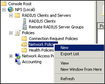
Open “Network Policies” under “Policies” and remove the 2 default policies called “Connections to Microsoft Routing and Remote Access server” and “Connections to other access servers” (or just make sure they are disabled)
Then, add a new policy
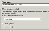
Set a name and leave the type of network access server to Unspecified
Click Next
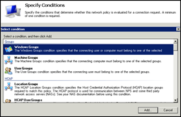
Under “Specify Conditions”, click “Add” and select “Windows Groups”. Click “Add” again
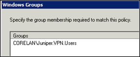
Click “Add Groups” and add the AD Group that contains the VPN users (Juniper.VPN.Users in my case)
Click OK
Click Next
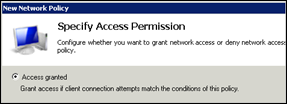
Set Access Permission to “Access granted” and click Next
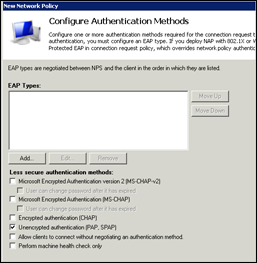
Authentication methods : deselect everything, except PAP, SPAP
Click Next. Click “No” when asked to see the corresponding Help Topic
Constraints : do not set constraints (unless you know what you are doing). Just Click next
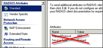
Configure Settings : Under “Standard”, remove the Framed-Protocol and Service-Type Attributes
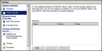
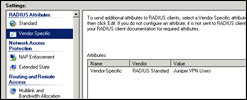
Go to Vendor Specific and click Add
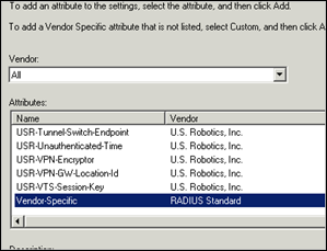
Set Vendor to All and select “Vendor-Specific” from the list. Click Add
Click Add again
Set Vendor Code to 3224. Select Yes. It Conforms
Click “Configure Attribute”
Set attribute number to 3, set format to String, and set Value to Juniper.VPN.Users
Click OK
Click OK again
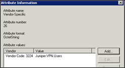
Verify that the new attribute is in the list and click OK again
Click Close
Click Next. Review the configuration settings
Click Finish
That’s it
Juniper : Define IP Pool / Subnet
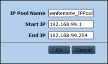
The goal is to assign IP addresses to Netscreen remote clients upon connecting to the Juniper via VPN. We’ll have to create an IP Pool for this. We will use 192.168.99.1-192.168.99.254 (which is in fact the 192.168.99.0/24 network) :
Objects – IP Pools – New
Note : this IP Pool should not overlap with any addresses in your network !
Juniper : create tunnel interface
We will use route based VPN, so we need to create a tunnel interface. This will allow us maximum flexibility, will allow us to put the VPN endpoint in the VPNBuffer zone, etc :
set int tunnel.3 zone VPNBuffer
set int tunnel.3 ip unnumbered interface eth0/2

get int tun.3
Interface tunnel.3:
  description tunnel.3
  number 20, if_info 1784, if_index 3, mode route
  link down
  vsys Root, zone VPNBuffer, vr trust-vr
  admin mtu 1500, operating mtu 1500, default mtu 1500
  *ip 0.0.0.0/0  unnumbered, source interface ethernet0/2
  *manage ip 0.0.0.0
  pmtu-v4 disabled
  ping disabled, telnet disabled, SSH disabled, SNMP disabled
  web disabled, ident-reset disabled, SSL disabled

  OSPF disabled  BGP disabled  RIP disabled  RIPng disabled  mtrace disabled
  PIM: not configured  IGMP not configured
  MLD not configured
  NHRP disabled
  bandwidth: physical 0kbps, configured egress [gbw 0kbps mbw 0kbps]
             configured ingress mbw 0kbps, current bw 0kbps
             total allocated gbw 0kbps
Juniper : set up routing
The IP Pool that we have created needs to be reachable. So we need to create proper routing. In fact, we need to send traffic towards the 192.168.99.0/24 network towards the new tunnel interface :
fw03-> set route 192.168.99.0/24 int tun.3
fw03-> get route | incl 192.168.99
         91    192.168.99.0/24          tun.3         0.0.0.0   S   20      1     Root
In addition to the route on the Juniper, all networks behind the Juniper need to be able to route back to the Juniper firewall in order to be communicate with hosts in the 192.168.99.0/24 network. We’ll assume that all hosts in the 192.168.1.0/24 network use the Cisco router as default gateway, and the Cisco is configured to route everything to the Juniper firewall. The Juniper firewall, in return, must have a route towards the 192.168.1.0/24 network, pointing to the Cisco.
fw03-> get route ip 192.168.1.1
 Dest for 192.168.1.1
--------------------------------------------------------------------------------------
trust-vr       : => 192.168.1.0/24 (id=87) via 192.168.0.8 (vr: trust-vr)
                    Interface ethernet0/1 , metric 0
Ok, routing looks good, let’s continue with the Juniper setup
Juniper : Define IKE user/group and External Group for XAuth via Radius
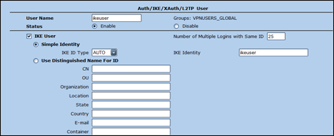
We’ll have to define an IKE user which will be used/shared by all Netscreen Remote clients. This will allow the client to set up Phase 1 of the VPN connection. Since we want to allow multiple users to use the same IKE user at the same time, we’ll need to put this IKE user in a user group and set the number of simultaneous connections to a number larger than 1
This is how it works :
Objects – Users – Local – New
Set the username, select IKE User and Simple Identity. Make sure the User Name and IKE Identity are the same.
Set the number of multiple logins to something higher than 1 (max. value is 25, if you need more, you’ll need to create multiple IKE users and spread the IKE users over your remote user base)
Set IKE ID Type to AUTO. Click OK to save
Next, create a group and place the ike user(s) in the group
Objects – Users – Local Groups – New
Next, go to Objects – Users – External Groups – New
The name of the group needs to match exactly with the value of the string that will be passed back from the Radius server upon authenticating. This may or may not be the same name as the AD group (depending on how you have configured the attributes in IAS). We have chosen to use the same name as the AD group name, which is Juniper.VPN.Users
Set the type to XAuth and press OK to save
Juniper : set XAuth Defaults
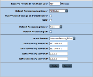
VPNs – AutoKey Advances – XAuth Settings
Set Authentication server to the Auth Server entry that was created earlier
Select the IP Pool and enter DNS/WINS settings. You need to set this because there is no other way to assign IP addresses to your VPN clients. If you don’t assign IP addresses, you will have lots of troubles getting the routing between VPN clients and your hosts to work properly.
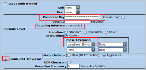
Juniper : Configure Phase 1
VPNs – AutoKey Advanced – Gateway – New
Pick a name, select Dialup User Group and select the newly created IKE group
Click Advanced
Set the PreShared Key
Select the outgoing interface (which needs to be the public interface, so in our case this is eth0/2). Set the Security Level to custom and select “pre-g2-aes128-sha).
Set the Mode to Aggressive. Enable NAT-T (this may not be required though – it depends on your setup)
Click Return and then OK to save
You may receive a similar warning :
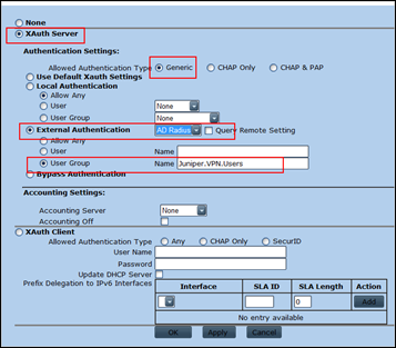
Click OK to accept. You should see the new Phase1 definition now. Click on the Xauth link next to your new Phase1
Select XAuth Server, and set the Authentication type to Generic.
Enable External Authentication and pick the Auth server (for Radius) from the list
Select User Group and fill out the group name
Click OK to save
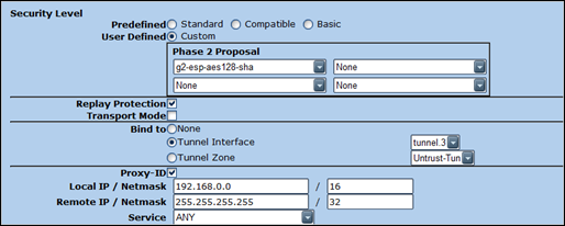
Juniper : Configure Phase 2
Go to VPNs – Autokey IKE – New
Set a new name and pick the Predefined Phase 1 that was created earlier
Click Advanced
Security Level : set to Custom and select g2-esp-aes128-sha from the list.
Enable Replay protection. Bind the VPN to the tunnel interface that was created earlier. (tunnel.3 in our case)
Enable proxy ID. Set Local IP to 192.168.0.0/16 and Remote IP to 255.255.255.255/32
Make sure Service is set to ANY
Click Return and then OK to save
Juniper : Configure Policies
We want to allow remote clients to access 192.168.0.6 and 192.168.1.8
Since the tunnel interface is in zone VPN, we need a policy from VPNBuffer to LAN
We’ll create some objects first
fw03-> set address VPNBuffer NetscreenRemoteUsers 192.168.99.0/24
fw03-> set address LAN Server1 192.168.0.6/32
fw03-> set address LAN Server2 192.168.1.8/32
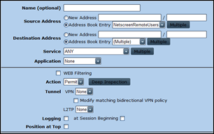
Next, create the policy (from VPNBuffer to LAN)
Source : NetscreenRemoteUsers
Destination : server1 (don’t add server2 yet)
Action : Permit (not tunnel ! We are using route based VPN, so action must be permit)
(screenshot contains entry for server2, but let’s assume it’s not there yet)
That’s it. We are now ready to configure the Netscreen Remote clients
Client : Configure Netscreen Remote
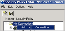
In the Security Policy Editor, create a new connection
Give the new connection a name (such as VPN to company)
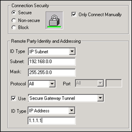
Set the connection security settings to “Secure” and enable “Only connect manually”
Remote party ID : enter the IP subnet that is used in the Local IP Proxy ID of Phase 2
Enable Use Secure Gateway Tunnel and Set the IP Address to the public IP of the Juniper VPN (which is 1.1.1.1) in our case
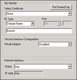
Next, click on the + (plus) symbol next to the new “VPN to company” connection and select “My Identity”
Set Certificate to None. Set ID Type to Domain Name and fill out the IKE identity/IKE username string from the IKE user that was created earlier.
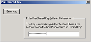
Click Pre-Shared Key and enter the Pre-Shared Key that was used when defining Phase 1
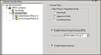
On the left hand side, select Security Policy
Select “Aggressive Mode”, enable PFS (DH Group2) and Enable Replay Detection
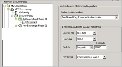
Open “Authentication (Phase 1)”, and select Proposal 1
Set authentication mode to Pre-Shared Key and Extended Authentication
Set Encrypt Alg to AES-128 and Hash alg to SHA-1
Set SA Life to seconds and enter 28800
Set Key Group to DH Group 2
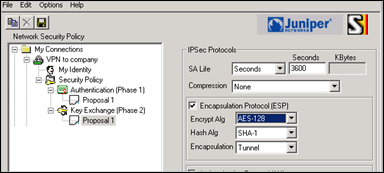
On the left side, open “Key Exchange (Phase 2)” and select Proposal 1
Set SA Life to Seconds and enter 3600
Leave compression to none. Enable ESP, set Encrypt Alg to AES-128 and Hash alg to SHA-1. Encapsulation = Tunnel. Leave AH (Authentication Protocol) disabled
Save the settings
Client : Connect
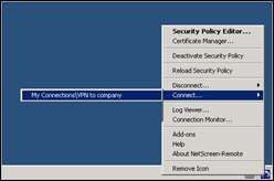
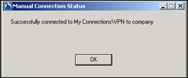
Try to connect : right-click on the Netscreen Remote Icon, choose “Connect” and select the new connection
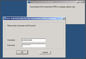
You should get a User Authentication prompt. Enter a username (DOMAIN\User or just the username) and the password of an account that is member of the AD Group
If you would have done a “debug auth radius” on the firewall while the Radius authentication took place, you should see that authentication was successful and that the XAuth group matches with the group that was passed back by the Radius server.
## 2009-01-22 21:41:12 : rad_parse() = rad_msg=0x02f50874{code=2, id=6, ...}
## 2009-01-22 21:41:12 : RadiusRecv: checking j:socket 75, socipv6 -1, sock 75, j:rad_id 6, rad_msg->id 6
## 2009-01-22 21:41:12 : RadiusRecv: Breaking for sock 75
## 2009-01-22 21:41:12 : is_resp_authenticator_valid: Valid Response authenticator
## 2009-01-22 21:41:12 : RadiusRecv: data on socket 75 for aq_ent 0x428db94, state 0x2, curr_server 1, curr_active 1
## 2009-01-22 21:41:12 : >>> rad_recv_auth(soc=3965916)
## 2009-01-22 21:41:12 : rad_attr_store_groups:adding first Juniper.VPN.Users
## 2009-01-22 21:41:12 : <<< rad_recv_auth() = rad_auth_resp=0x043123b0{authed=1 priv=0 role=0 id=6}
## 2009-01-22 21:41:12 : is_resp_authenticator_valid: Valid Response authenticator
## 2009-01-22 21:41:12 : radius_recv_auth_resp: RESPONSE AUTH VALID (was a Accept)
## 2009-01-22 21:41:12 : group_check_ok: ugx_name Juniper.VPN.Users, group_item_ptr 0x2c4f914, username corelan\peter
## 2009-01-22 21:41:12 : is_rad_group_in: compare Juniper.VPN.Users with Juniper.VPN.Users
## 2009-01-22 21:41:12 :  MATCHED
## 2009-01-22 21:41:12 : group_check_ok: ext group Juniper.VPN.Users present
## 2009-01-22 21:41:12 : radius_recv_auth_resp: auth 0x428db94, id 6,  GROUP MATCHED have Juniper.VPN.Users
## 2009-01-22 21:41:12 : radius_recv_auth_resp: auth 0x428db94, id 6,  AUTHENTICATED
## 2009-01-22 21:41:12 : rad_groups_free: freeing: next_item_ptr->group_name Juniper.VPN.Users
## 2009-01-22 21:41:12 : >>> RadiusRecv(aq_ent={un='corelan\peter', fl=3, as_id=2, rt=0, rt1=0, rt2=0})
## 2009-01-22 21:41:12 : <<< RadiusRecv(aq_ent={rad_state=7}) = 1
## 2009-01-22 21:41:12 : RadiusRecv: result 1
## 2009-01-22 21:41:12 : get_auth_radius_clnt_session_id: entered
Verify the VPN connection on the Juniper :
fw03-> get ike cookies

IKEv1 SA -- Active: 1, Dead: 0, Total 1

1097182f/0006, 1.1.1.2:500->1.1.1.1:500, PRESHR/grp2/AES128/SHA, xchg(5) (IKE_NetscreenRemote/grp7/usr10)
resent-tmr 322 lifetime 28800 lt-recv 28800 nxt_rekey 28484 cert-expire 0
responder, err cnt 0, send dir 1, cond 0x30
nat-traversal map not available
ike heartbeat              : disabled
ike heartbeat last rcv time: 0
ike heartbeat last snd time: 0
XAUTH status: 100
DPD seq local 0, peer 762132764

IKEv2 SA -- Active: 0, Dead: 0, Total 0

fw03-> get sa active
Total active sa: 1
total configured sa: 2
HEX ID    Gateway         Port Algorithm     SPI      Life:sec kb Sta   PID vsys
00008001<         1.1.1.2  500 esp:a128/sha1 a12260dd  3289 unlim A/-    -1 0
00008001>         1.1.1.2  500 esp:a128/sha1 1259e395  3289 unlim A/-    -1 0

fw03-> get sa id 0x8001
index 2, name ESP_NetscreenRemote, peer gateway ip 1.1.1.2. vsys<Root>
auto key. tunnel if binding node, tunnel mode, policy id in:<-1> out:<-1>
id hash: >00>ce>69>fb>fb>e3>2d>0e>76>44>4b>67>3c>9a>fa>0d>43>79>6d>b1
 vpngrp:<-1>. sa_list_nxt:<8>. parent_sa_id:<8>.
tunnel id 32769, peer id 0, NSRP Local.     dialup, dynamic member.   site-to-site. Local interface is ethernet0/2 <1.1.1.1>.
  esp, group 2, a128 encryption, sha1 authentication
  autokey, IN active, OUT active
  monitor<0>, latency: 0, availability: 0
  DF bit: clear
  app_sa_flags: 0x2400437
  proxy id: local 192.168.0.0/255.255.0.0, remote 192.168.99.1/255.255.255.255, proto 0, port 0
  ike activity timestamp: 887422404
  DSCP-mark : disabled
nat-traversal map not available
incoming: SPI a12260dd, flag 00004000, tunnel info 40008001, pipeline
  life 3600 sec, 3282 remain, 0 kb, 0 bytes remain
  anti-replay on, last 0x6, window 0x3f, idle timeout value <0>, idled 280 seconds
  next pak sequence number: 0x0
  bytes/paks:360/6; sw bytes/paks:360/6
outgoing: SPI 1259e395, flag 00000000, tunnel info 40008001, pipeline
  life 3600 sec, 3282 remain, 0 kb, 0 bytes remain
  anti-replay on, last 0x0, window 0x0, idle timeout value <0>, idled 318 seconds
  next pak sequence number: 0x0
  bytes/paks:0/0; sw bytes/paks:0/0
Verify the XAuth sessions and verify that an IP was assigned to the VPN session :
fw03-> get xauth active

GW Name              Login           Auth By    GW IP           Private IP      Last Login     Session Timeout   Idle Timeout
IKE_NetscreenRemote   corelan\peter  AD Radius         1.1.1.2    192.168.99.1 255.255.255.255  2009-01-22 21:13:10         0      0
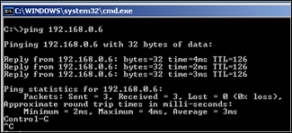
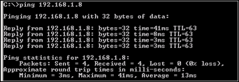
Verify that the client can access resources in all networks :
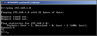
Verify that it cannot access networks that are not allowed by the policy
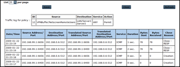
Adjust the policy, add the 192.168.1.8/32 host (Server2) as allowed destination and see if traffic to the second network works as well :
© 2009 – 2021, Peter Van Eeckhoutte (corelanc0d3r). All rights reserved.
