13,348 views
 Windows XP L2TP over IPSec dialup client VPN to a Juniper ScreenOS firewall, using Certificates
Before looking at the various configuration steps, we’ll have to take the following assumptions into account :
– We don’t want to use the Netscreen Remote client, but we want to use the Windows XP built-in dialup VPN technology that allows us to build PPTP or L2TP/IPSec connections. Juniper screenOS does not support PPTP (which is not as safe as IPSec anyway)
– The XP clients will have dynamic IP’s. They are either directly connected to the internet, or connected behind a firewall/router that is capable of forwarding ESP packets. Keep in mind that nat-traversal cannot be used. (So if the client is behind a NAT router, it will not work out of the box (because it will try to send fqdn as peer ID instead of IP address). There is a fix, but it requires you to edit a dll file. You can read more about this at http://www.juniperforum.com/index.php?topic=7706.new;topicseen
– Because the client IP addresses can be dynamic, authentication needs to happen using certificates. (After all, identification is based on IP address or ASN1-DN peer ID’s. Juniper screenOS also supports fqdn and u-fqdn ID types, but this is not support on XP)
Since you will be using certificates, you may want to set up your own PKI. You can find more information on how to set up a Windows 2008 based PKI in this post. Keep in mind that the reachability of the CRL will be very important.
Network layout
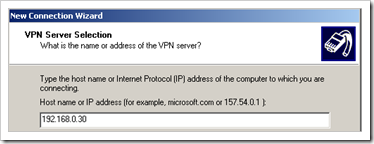
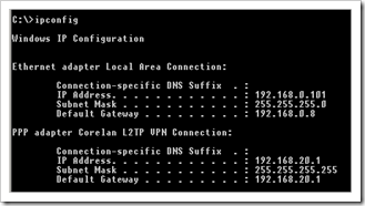
The remote client has IP 192.168.0.101. It will be connecting to the public IP of the Juniper firewall, which, in my testlab, is 192.168.0.30. When connected, the client will receive an IP in the 192.168.20.1 – 100 range. The network it needs to have access to is 192.168.2.0
The internet facing interface on the ssg5 is in zone “Public”, the internal (private) interface is in zone “LAN”
Create and install a certificate on each client
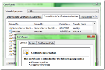
First of all, install the root certificate of the PKI into the “Trust Root Certificate Authorities” on each client that needs to connect to your network. You can do this via a Group Policy, or manually.
My internal CA is called socrates.
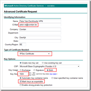
Next, go to the certificate server website and request a new IPSec certificate. You’ll need to submit an advanced request in order to be able to select the “IPSec Certificate” template
On Windows XP, the request should look like this :
(note that with IE7 you cannot set the certificate to be stored in the local machine store. This is why I enabled the private key to be exportable, so you can export it, and import it manually in the local machine store)
In both cases, make sure the Email address is filled out, because this will be used as peer ID
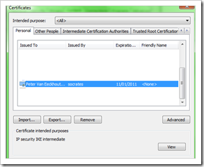
When the certificate has been installed, Export it to a file (including the private key) and import it back into the local machine store :
IE – Options – Content – Certificates – Personal
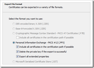
Export (including the private key). Feel free to delete the private key if the export is successfull.
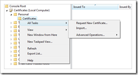
Open a mmc, select the certificates snap-in and select “Computer account”
Open the Certificates, go to “Personal – Certificates” and import the certificate
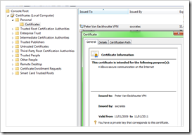
Verify that it was installed properly and that it includes the private key :
Either way, make sure
– the root certificate is installed in the Trust Root Certificate Authorities
– the new IPSec certificate is installed in the local computer store
Configure Juniper ScreenOS for certificates
First of all, make sure the time and DNS settings of your Juniper firewall are correct. You will need DNS to be able to connect to the CRL URL, and the time settings are required to validate whether a certificate has expired or not.
Next, create a certificate for your Juniper device.
Start by importing the root certificate to the device. From the PKI website, download the root CA certificate in .cer format.
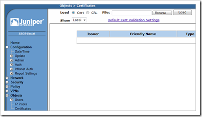
Go to the Juniper firewall WebUI , navigate to “Objects” – “Certificates”
Click the “browse” button and locate the .cer file Click “load” to load the CA certificate.
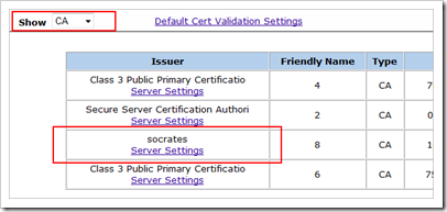
Set “show” to CA and verify that the root cert was loaded properly
Click the “new” button to create a new certificate
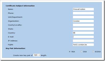
Fill out the Name, Organization, fqdn
Set the type to RSA
Set the length to 1024
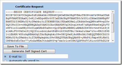
Click “Generate” to create a new request and wait until the request string is shown. This can take a couple of minutes.
Copy the text in the certificate request to the clipboard
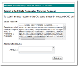
Go to the PKI certsrv website, Submit a new request. Choose ‘advanced’ request.
Click “Submit a certificate request by using a base-64-encoded…”
Paste the request string in the “Saved Request” box and click Submit
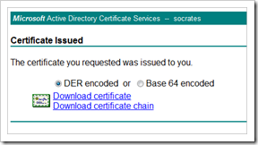
When the certificate is issued, pick it up and save it to file
Go back to the Juniper device, under certificates, browse to the new .cer file, and load it
Look at the details of this new certificate and verify that it contains the correct data
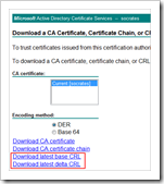
Next, import the CRL from your CA. Go to the PKI website again, and download the CRL file to disk
On the Juniper device, under certificates, Set the type to CRL
Use browse to locate the crl file and click “load” to load it
Configure Juniper ScreenOS for incoming L2TP/IPSec dialup connections
First, define the IP pool out of which IP addresses will be assigned to the end users. This range of IP addresses can not be used on the firewall yet. It must be unique
set ippool "L2TP_VPN_Pool" 192.168.20.1 192.168.20.100
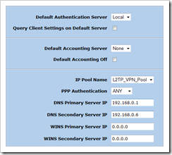
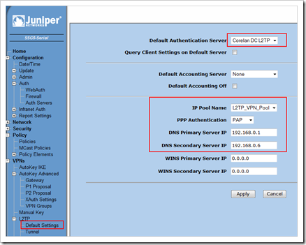
Set the L2TP defaults : assign the IP pool to l2tp, set authentication, DNS and WINS options :
(VPNs – L2TP – Default Settings)
set l2tp default ippool "L2TP_VPN_Pool"
set l2tp default dns1 192.168.0.1
set l2tp default dns2 192.168.0.6
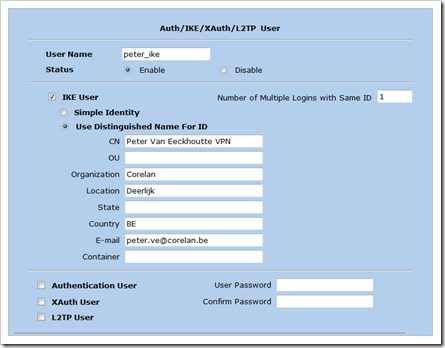
Create IKE / L2TP Users
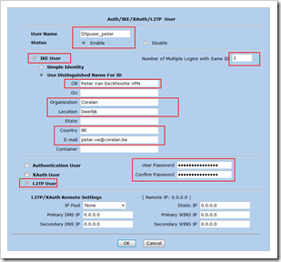
Under “Objects” – “Users”, click “New”
Make sure the CN , E-Mail, Organization, Location, etc match with the certificate that was created for the client computer earlier. You will have to create an IKE user configuration for each user.
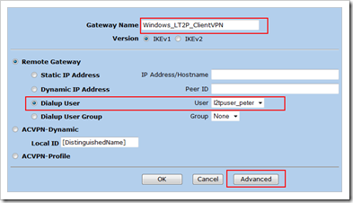
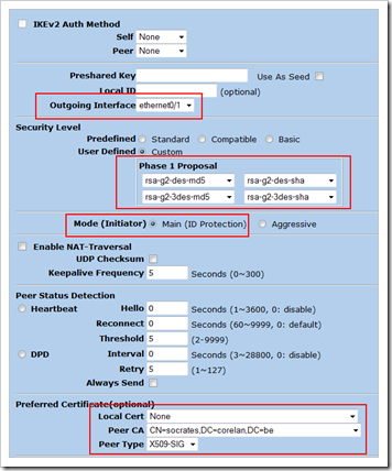
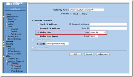
Create Phase 1 definition (IKE Gateway)
(Click “advanced”)
Click “Return” and “OK” to save
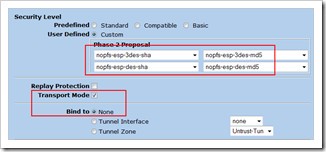
Create Phase 2 (AutoKey IKE) definition
Click “Advanced”
Click “Return” and then “OK” to save
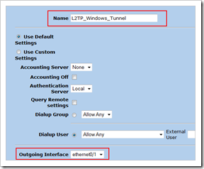
Create the L2TP Tunnel
VPNs – L2TP – Tunnel “New”
Pick a name and set the outgoing interface to the public interface (eth0/1 in our case)
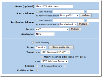
Create a policy that will invoke the L2TP tunnel
From Public to Lan
Create the dialup connection on XP
First of all, make sure there is no 3rd party VPN (IPSec) client/driver installed, as this one may interfere with the Windows IPSec driver. Make sure the IPSec service is started on the XP client
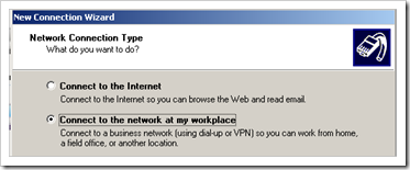
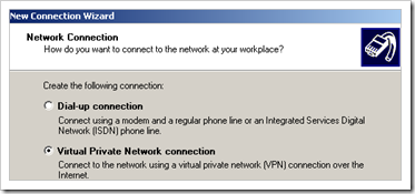
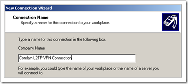
Control Panel - Network Connections – Create a new connection
Finish and save the new connection.
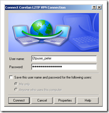
The “connect …” dialog will open. Enter the l2tp username and password
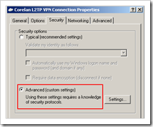
Click “Properties” and open the “Security” tabsheet and set the Security Options to “Advanced (custom settings)”
Click “settings”
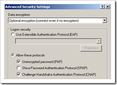
Under “Data Encryption”, choose “Optional encryption”.
Protocols : allow PAP and CHAP. Juniper does not support MS-CHAP. Accept the warning about passwords being sent in the clear when you only use PAP/CHAP. That is ok, because the IPSec connection will be up first, and then the L2TP (and then PPP) session will be activated. So don’t worry about your password being sent in the clear.
Click OK
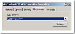
Go to the “Networking” tab and set the Type to L2TP IPSec VPN
Click OK to save
You are now ready to build the dialup VPN connection.
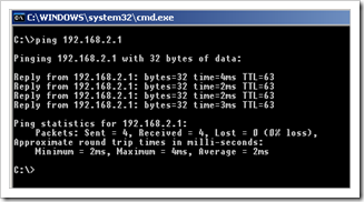
Access to resources in the 192.168.2.0 network should work, as long as they have a route back to 192.168.20.x
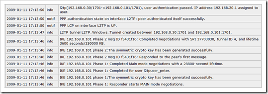
On Juniper, you should see this :
get ike cookies

IKEv1 SA -- Active: 1, Dead: 0, Total 1

1113f/0003, 192.168.0.101:500->192.168.0.30:500, RSA_SIG/grp2/3DES/SHA, xchg(2) (Windows_LT2P_ClientVPN/grp-1/usr1)
resent-tmr 322 lifetime 28800 lt-recv 28800 nxt_rekey 28629 cert-expire 63056824
responder, err cnt 0, send dir 1, cond 0x0
nat-traversal map not available
ike heartbeat              : disabled
ike heartbeat last rcv time: 0
ike heartbeat last snd time: 0
XAUTH status: 0
DPD seq local 0, peer 0


IKEv2 SA -- Active: 0, Dead: 0, Total 0


get sa active

Total active sa: 1
total configured sa: 2
HEX ID    Gateway         Port Algorithm     SPI      Life:sec kb Sta   PID vsys
00000004<   192.168.0.101  500 esp:3des/md5  37703030  3427  244M A/-     7 0
00000004>   192.168.0.101  500 esp:3des/md5  358e0e39  3427  244M A/-    -1 0

get l2tp all

   ID       L2TP Name       User        Peer IP         Host   KpAlv Intface
--HEX--- --------------- -------------- --------------- ------ ----- -------
00000001 L2TP_Windows_Tu all-l2tp-users 0.0.0.0                   60 eth0/1


get l2tp all active

L2TP Name       Tunnel Id Peer Address    Port Peer Host    Calls State   t_info
--------------- --------- --------------- ---- ------------ ----- ------- --HEX---
L2TP_Windows_Tu ( 89/  1) 192.168.0.101   1701 xptest1          1 estblsh 80008059
L2TP_Windows_Tu (  0/  0) 0.0.0.0            0                  0    idle 80000001
Troubleshooting
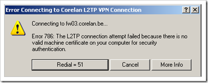
“The L2TP connection attempt failed because there is no valid machine certificaet on your computer for security authentication”
– verify that the IPSec certificate is installed in the Computer store
– verify that the root certificate is installed in the Trusted Root Certificate Authorities
What if I want to use Radius to authenticate the users, in conjunction with the certificate ?
No problem. In the step-by-step above, I have created one user that is used as IKE (Phase1) and L2TP (authentication after IPSec tunnel is up) at the same time. You can of course create an IKE-only user (so the certificate would still be validated), and use an auth server (Radius) to validate the L2TP users
This is how it works
First, create an IKE user. If you want to validate certificates, you will always need an IKE user for each user account. In this scenarion, the user name is not that important. Just make sure to enable the user, select IKE only, set the number of logins to 1, and set to use the DN for ID. Fill out the properties to they match with the certificate. Do NOT select L2TP user. Just save this new user. This will make sure any Phase1 connection with this certificate is accepted.
Again, you can only have one simultaneous connection per ike user/certificate combination, so you’ll have to create an IKE user for each certificate if you want to use certificates. I agree, it does not scale very well, but hey – it works.
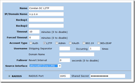
Next, create a new auth server for L2TP. I’ll use a Windows based IAS for this, so I can use Active Directory accounts for user authentication.
Set a good name, set the IP address of the IAS server. Set Account Type to L2TP. Select Radius and set the shared secret.
In Active Directory, create your l2tp user accounts, put them in a L2TP.User group, and create an IAS policy to authenticate users when they are member of this group.
(If you don’t know how to set up the IAS server Radius Client and IAS Policy, check out this post). Make sure, in the authentication page of the IAS Policy, to only select PAP as accepted authentication method.
Next, on the Juniper firewall, go to the L2TP Default settings. Set the default authentication server to your newly created auth user. Set PPP Authentication to use PAP.
Edit the Phase 1 (Gateway) and select your IKE-only user
The Phase2 settings, L2TP Tunnel and the policy will remain the same as explained earlier in this post.
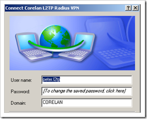
In the properties of the dialup connection on the XP client, make sure the logon domain is displayed. THe other settings can remain the same.
Enter the username, password and domain of a user account in your active directory, that will match the IAS policy for authentication L2TP users.
Connect, and it should work. (If not, then maybe Phase1 of the old L2TP tunnel is still active. Remove all Phase1 sa’s using “clear ike-cookie all”)
You can troubleshoot the Radius authentication process using “debug auth radius”
© 2009 – 2021, Peter Van Eeckhoutte (corelanc0d3r). All rights reserved.

